5
05.01
5.5 ”ANA module” control board
5-142
© Siemens AG 2008 All Rights Reserved
SIMODRIVE 611 Configuration Manual (PJU) – 05/2008 Edition
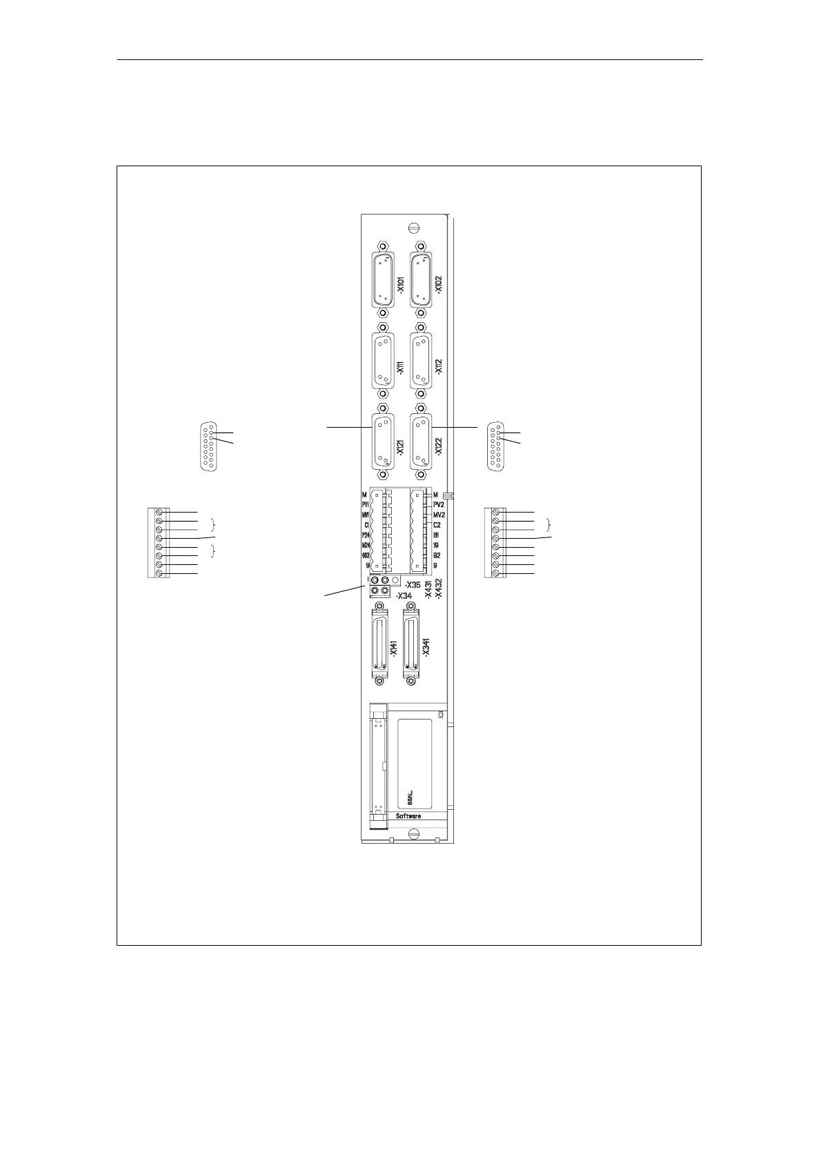
DACs
Measuring system (encoder connection)
X101
Sensor detection
X111
External drive amplifier
X121
Drive bus
X141
Equipment bus
X151
Axis 1 Axis 2
Drive bus
X341
C2
B1
BERO input, axis 1
24 V switched, axis 1
External 26.5 V supply
Internal +24 V enable voltage
24 V switched, axis 2
BERO input, axis 2
Power enable, term. 663
Internal 0 V enable voltage
Internal +24 V enable voltage
Electronic ground
Reserved, do not use
Electronic ground
Reserved, do not use
+
–
+
–
+
–
C1
M24
P24
M
663
9
19
M
B2
9
PV1
MV1
PV2
MV2
X431 X432
1
89
15
n
set
, $10 V
n
set
, reference ground
1
89
15
n
set
, $10 V
n
set
, reference ground
External drive amplifier
X122
Measuring system (encoder connection)
X102
Sensor detection
X112
Fig. 5-12 ANA control unit (2–axis)
ANA control unit
5 Control Units