6
05.01
6.7 DC link options
6-192
© Siemens AG 2008 All Rights Reserved
SIMODRIVE 611 Configuration Manual (PJU) – 05/2008 Edition
Table 6-20 Braking power of the UI and pulsed resistor modules (PR)
Description External PR 0.3/25 kW
1)
External PR Plus 1.5/25 kW
Order number 6SN1113–1AA00–0DA0 6SL3100–1BE22–5AA0
Can be used
for
28 kW UI module 28 kW UI module
PR module 6SN1113–1AB0V–0BAV
S Attenuation: 0...230 kHz 3 dB
S Must be used together with HFD commutating reactor for damping
Pn 0.3 kW 1.5 kW
P
max
25 kW 25 kW
E
max
7.5 kWs 180 kWs
Dimension drawings, refer to Chapter 12
1) External PR can also be used for damping after a protecting measurement on the HFD reactor.
The resistor can be mounted either horizontally or vertically.
red, blue, PE (green yellow), each 1.5 mm
2
Shielded 3 m connecting cable, can be extended up to max. 10 m
PE
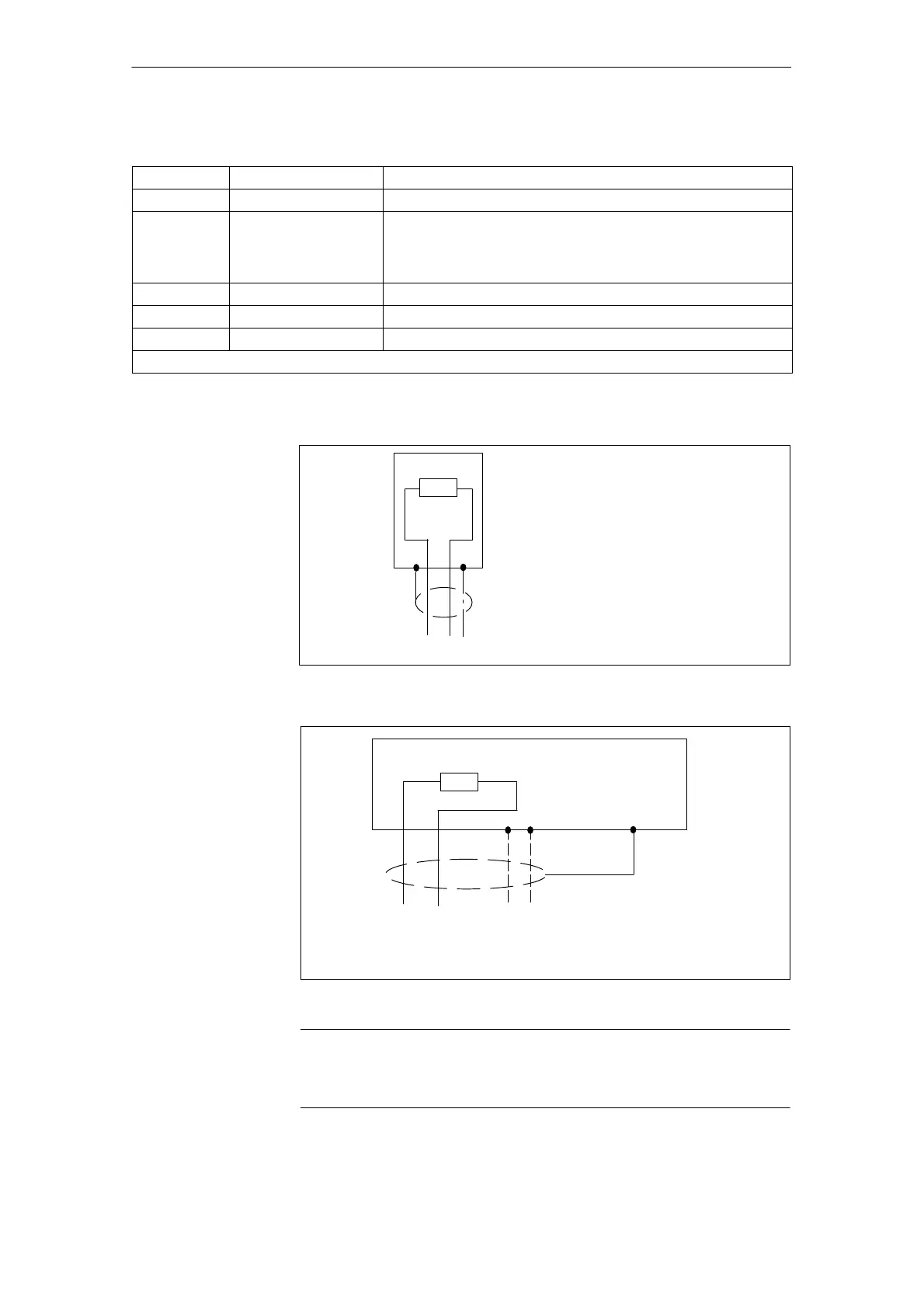
Fig. 6-20 Connection for external pulsed resistor 0.3/25 kW
The shield is connected through a PG gland
Shielded connecting cable (braided shield), cross–section 2.5 – 4 mm
2
,
max. length 10 m
PE
V/L2U/L1/C/L+
W/L3/D/L–
3R 1R PEPE
Fig. 6-21 Connection for external PR for braking power ratings up to 1.5/25 kW
Note
Conductors that are not used in multi–conductor cables must always be
connected to PE at both ends.
Mounting
positions
6 Infeed Modules 11.0505.08