8
05.01
8.2 Infeed modules
8-237
© Siemens AG 2008 All Rights Reserved
SIMODRIVE 611 Configuration Manual (PJU) -- 05/2008 Edition
External switching voltage for the coil circuit of the line contactor
Is used to supply the coil circuit of the internal line contactor only at the 80 kW
and 120 kW I/R modules (do not connect between the I/R module and reactor).
Fuse: I
r
≥ 4 A, version gL
2--ph. 360 to 457 V AC/45 to 53 Hz; 400 to 510 V/57 to 65 Hz
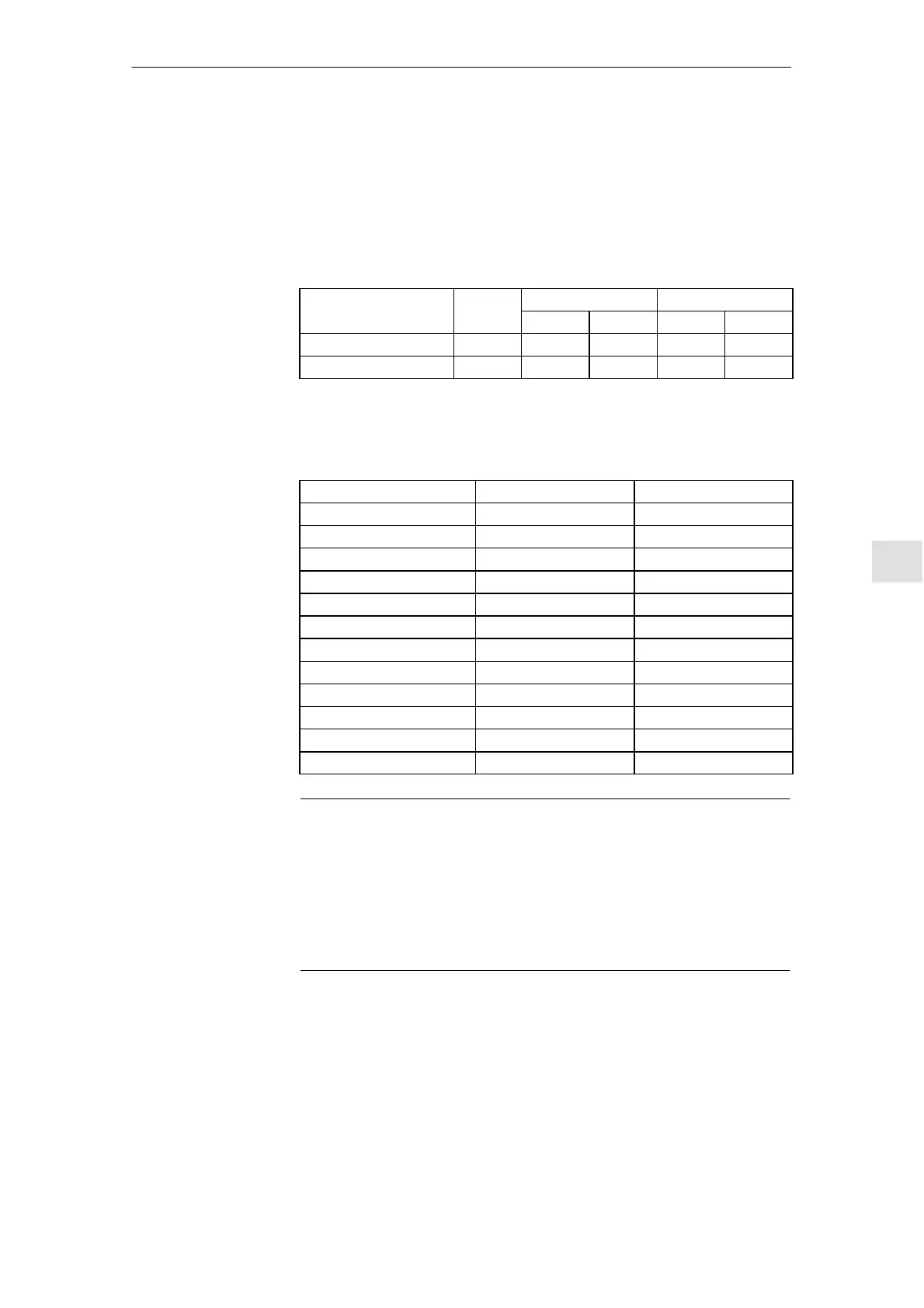
Table 8-1 Technical data of the internal line and pre--charging contactor
I/RF module
Type Pull--in power [VA] Holding power [VA]
50 Hz 60 Hz 50 Hz 60 Hz
6SN1 14j--1BB0j--0EA1 3TK48 330 378 36 44.2
6SN1 14j--1BB0j-- 0 F A 1 3TK50 550 627 32 39
Matching transformer for the coil connections L1, L2 at the line supply voltage 230 V and
380 V; for two 5TK5022--0AR0 contactors.
Table 8-2 Matching transformer SIDAC 1--phase autotransformer
For 50 Hz line supplies For 60 Hz line supplies
Type 4AM4096--0EM50--0AA0 4AM4696--0EM70--0F A0
Throughput rating [VA] 80 80
Input voltage [V] 380/230 380/230
Output voltage [V] 415 (min. 360/max. 458) 460/415
Output current [A] 0.193 0.19...0.17
Insulating material class T40/B T40/B
Applicable standard EN 61558--13 VDE 0532
Frequency [Hz] 50/60 50/60
Vector group IA0 Ii0
Degree of protection IP00 IP00
Dimension sketch PD10 T8/2 LV 10
for voltage fluctuations +10% --13.2 % +10% --13.2 %
Note
If, for the 80/104 kW or 120/156 kW I/R module, the line supply voltage at
terminals L1, L2 fails or fuses F1, F2 trip, then only the pulses in the I/R module
are cancelled and the internal line contactor drops --out.
This is displayed using the ”line fault” LED, the ready relay and also the
contactor signaling contacts. In this case, in order to re --close the internal line
contactor, terminal 48 must be inhibited (de--energized) and re --energized after
≥one second or the unit must be powered--down/powered --up.
Reset
The fault signal is reset using a pushbutton (pulse edge) between terminal R
and terminal 15.
For the SIMODRIVE 611 universal HRS control unit, the reset is effective if, in
addition, terminal 65 ”controller enable” is also inhibited.
Terminals L1, L2
Terminal R
Im
o
n
C
cu
Info
m
on11.05
 Loading...


