8
05.01
8.7 Circuit examples =1 to =9 with SIMODRIVE 611
8-280
© Siemens AG 2008 All Rights Reserved
SIMODRIVE 611 Configuration Manual (PJU) – 05/2008 Edition
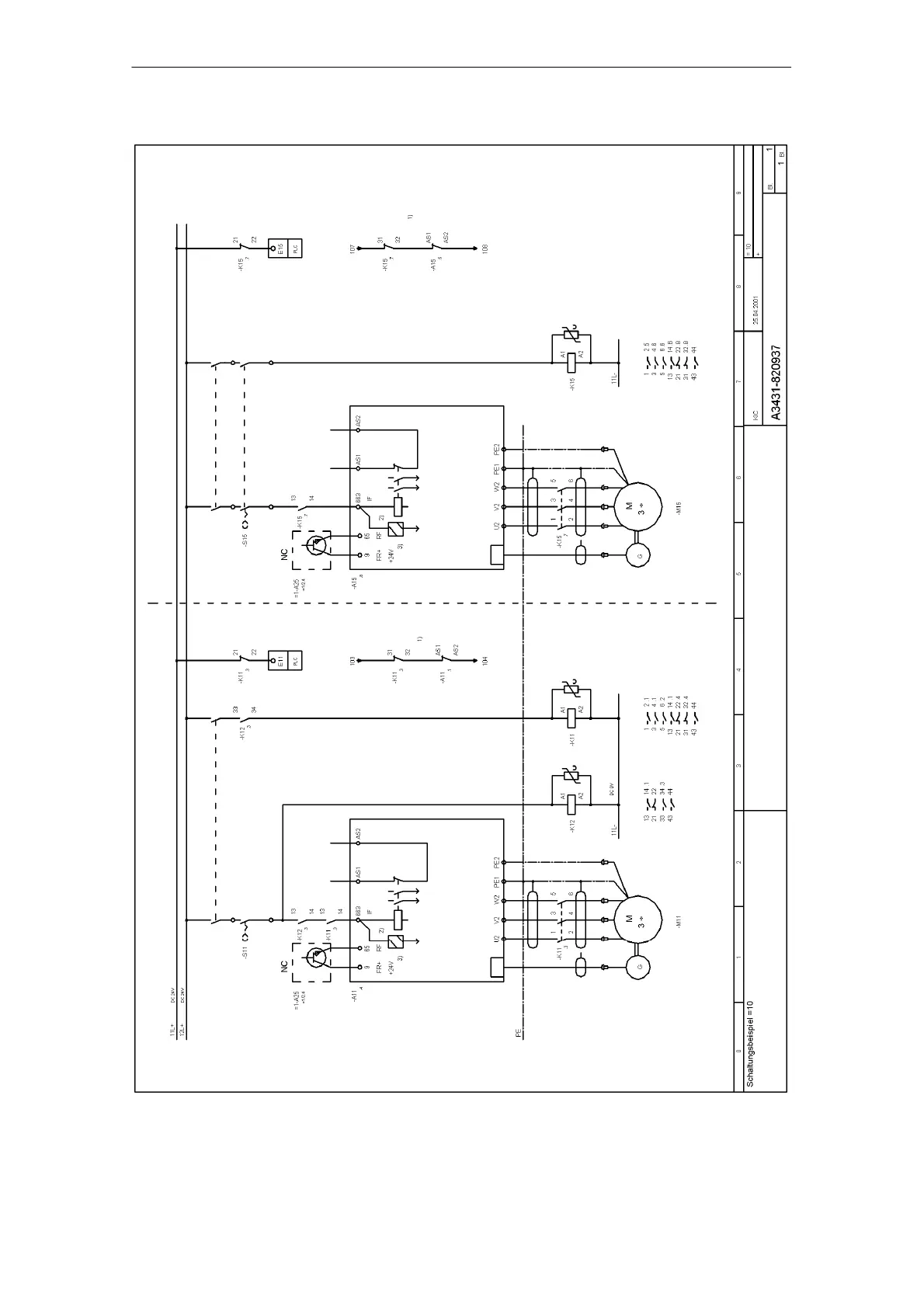
1) Add monitoring circuit to the
start–circuit drive =4–K31/Y33–Y34
, circuit 4
2) The terminal 663 pulse release
must be switched off 10 ms earlier
, before the power contacts open
in the motor.
The terminal 663 can be triggered
simultaneously or
delayed after closing
the power contacts.
3) WARNING
The circuit can be used only with
control units with approx. 1 ms
non–delayed pulse inhibit
using terminal 663.
Delayed stop
Delayed stop
Principle schematic 1
1–channel switch
Principle schematic 2
2–channel switch
Drive module Drive module
Drive
off/on
Drive
off/on
Drive
Off
Drive
Off
Power contactors in the motor circuit (if required)
Fig. 8-24 =9 Power contactors in the motor circuit; Sheet 1/1
8 Im
ortant Circuit Information 05.08
 Loading...


