8
05.01
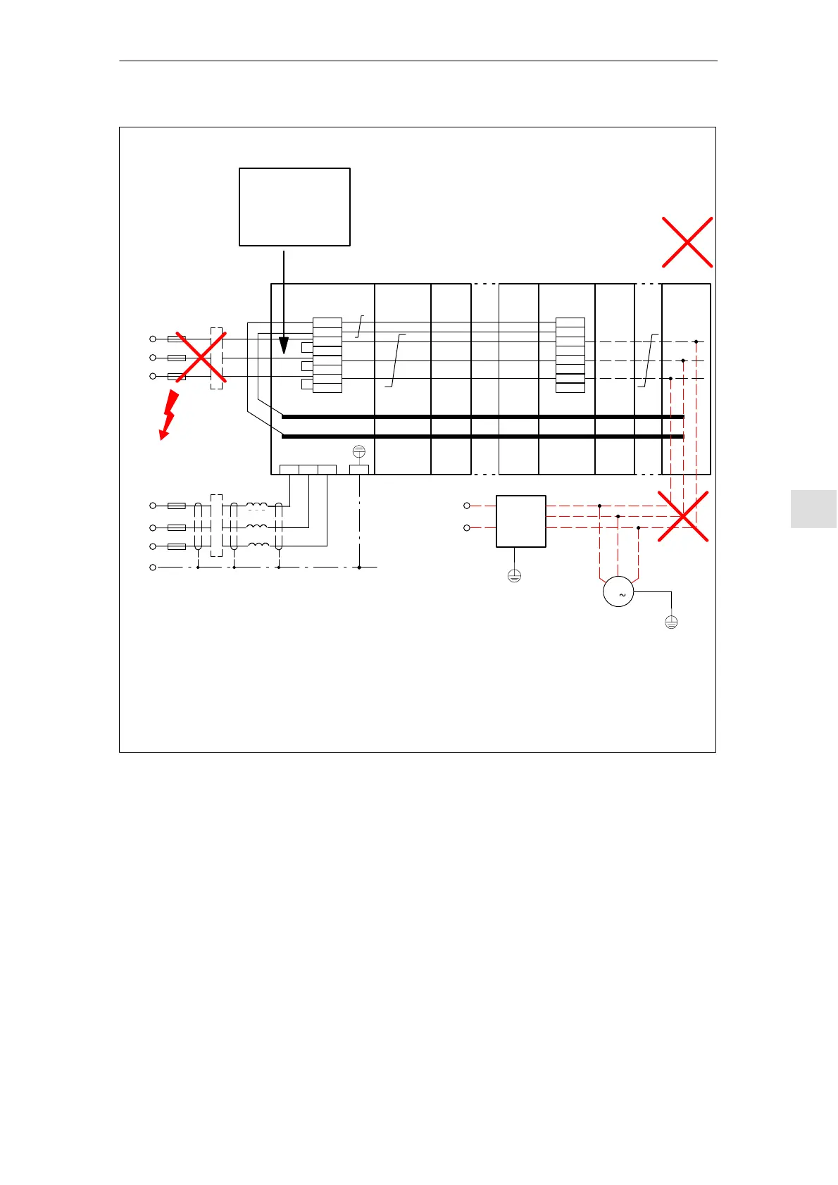
8.15 Examples of correctly and incorrectly connecting NE
8-321
© Siemens AG 2008 All Rights Reserved
SIMODRIVE 611 Configuration Manual (PJU) – 05/2008 Edition
+ MM 3 /
+ MM 4
e.g. NCU PMxx
P600
M600
U1 V1 W1 PE
PMxx PMxx
X181
M500
P500
2U1
1U1
2V1
1V1
2W1
1W1
X181
M500
P500
2U1
1U1
2V1
1V1
2W1
1W1
Incorrect!
L1
L
K
F
N
(X A)
Filter (X kW)
PE
L2
L3
Schematic diagram
L1
F
N
(T10 A)
Filter (X kW)
L2
L3
1)
2)
Consequences when incorrectly connected to the line supply:
1) Arcing with respect to PE in the power supply
Refer to the use of HF/HFD commutating reactor to prevent system oscillations in Chapter 6.4.
Consequences when the system oscillates: Burned overvoltage limiting module
2)/3)/4):
More than four monitoring modules:
Additional loads:
Consequence: Burnt PC board tracks on the line infeed module (NE module) power supply
M
3
3)
e.g.
24 V DC
e.g.
SITOP
20 A
4)
Connection
e.g. overvoltage
limiting module (this
is mandatory for UL)
1)
+ MM 5
+ MM 6
+ MM 7
NE MM
Twisted
cable
Fig. 8-40 Additional examples for frequent faults/mistakes when connecting to the line supply
8 Im
ortant Circuit Information
 Loading...


