9
05.01
9.1 Installation and connecting–up regulations
9-331
© Siemens AG 2008 All Rights Reserved
SIMODRIVE 611 Configuration Manual (PJU) – 05/2008 Edition
G
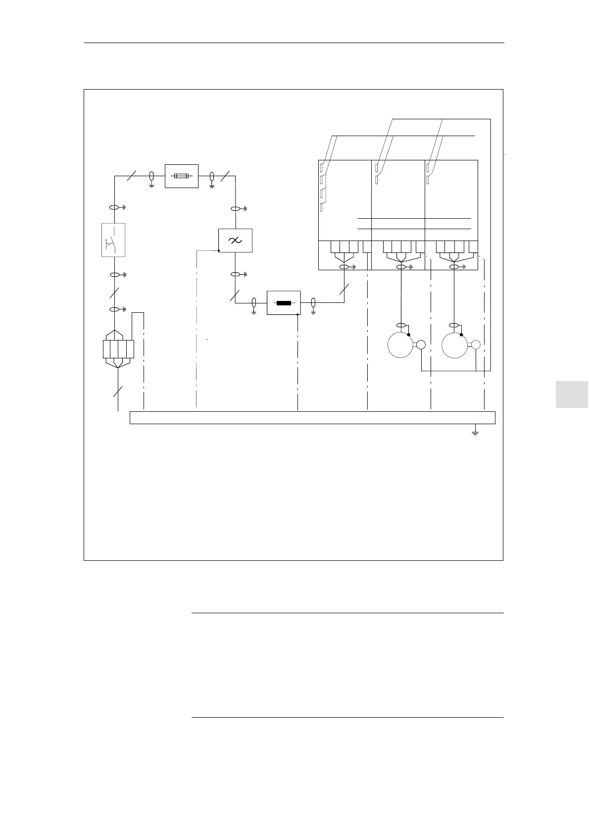
Functional
cables
PE rail electrically connected over a large surface area to the cabinet mounting panel
3)
Cabinet mounting panel
1)
I/R module
or
UI module
2)
MSD module FD module
P600
M600
2)
M
M
1)
1)
1)
1)
Supply
system
1) Shield connection through the largest possible surface area to the cabinet mounting panel.
2) Shield connection at the module–specific connecting plate.
Encoder cables
1)
1)
Fuses
Input terminals
Main switches
PE
PE
L2
L3
L1
PE
V1U1 W1
3) PE cables can be, alternatively, connected using a PE rail also observing EN50178
(protective connections).
V2U2
W2
PEV2U2
W2
4
3
3
3
Reactor
1)
1)
3
3
LOAD
LINE
PE
Filter
PE
2)
G
4) Permissible commutating reactors for I/R module, sinusoidal operation – refer to Sections 3.4.2 and 3.1
Permissible commutating reactor for 28 kW UI module, refer to Section 3.4.2
A clearance of > 100 mm must be provided above the HFD reactor when routing the cable in the electrical
cabinet.
4)
Note:
The filter may only be mounted with the line supply connection at the bottom (downwards).
Cables longer than 1 m must be shielded. If unshielded connections are used, an adequate
separation > 20 cm must be observed for cables subject to coupling!
Fig. 9-1 Connecting diagram for line filters for 5 kW and 10 kW U/I modules and for 16 kW to 120 kW I/R modules.
The connecting diagram also applies to –28 kW UI, – however as a result of the unregulated infeed, 6–pulse
squarewave current is drawn.
Note
1. The EMC measures described above ensure CE compliance with the EMC
Directive.
2. Alternative measures can be applied, e.g. routing behind mounting plates,
suitable clearances, under the assumption that they have similar results.
3. This excludes measures that relate to the design, installation, and routing of
motor power cables and signal cables.
9 Cabinet Desi
n and EMC05.08