9
05.01
9.1 Installation and connecting--up regulations
9-339
© Siemens AG 2008 All Rights Reserved
SIMODRIVE 611 Configuration Manual (PJU) -- 05/2008 Edition
Length of cable
Twisted, shielded
above 1 m cable length
max 5 m! (in
conjunction with
SIMODRIVE POSMO
SI/CD/CA, the
guidelines correspond
to the User Manual
SIMODRIVE POSMO
SI/CD/CA)
Equipotential bonding cable is routed along
the mounting panel close to the
P600/M600 conductors.
For the NC control system
Adapter terminals, Order No.
For module width, 50 -- 200 mm
6SN1 161--1AA01--0BA0
For module width, 300 mm
6SN1 161--1AA01--0AA0
2)
1) The drive group has more than six drive axes. This is the reason that round drive bus cables are used
in the complete group. Further, the shields of those round drive bus cables that are used to jumper/bridge
”Gaps in the module group” must be clamped/connected to the associated module housing!
Schematic
diagram
Round cable
Terminating connector
for the drive bus
Cable length, max. 5 m
2) Danger notice!
Do not use for module
widths 50 -- 200 mm.
Danger of death
because the contact
safety is endangered!
!
Pay attention to the
cooling!
Connection: short--circuit resistant,
cable/busbar
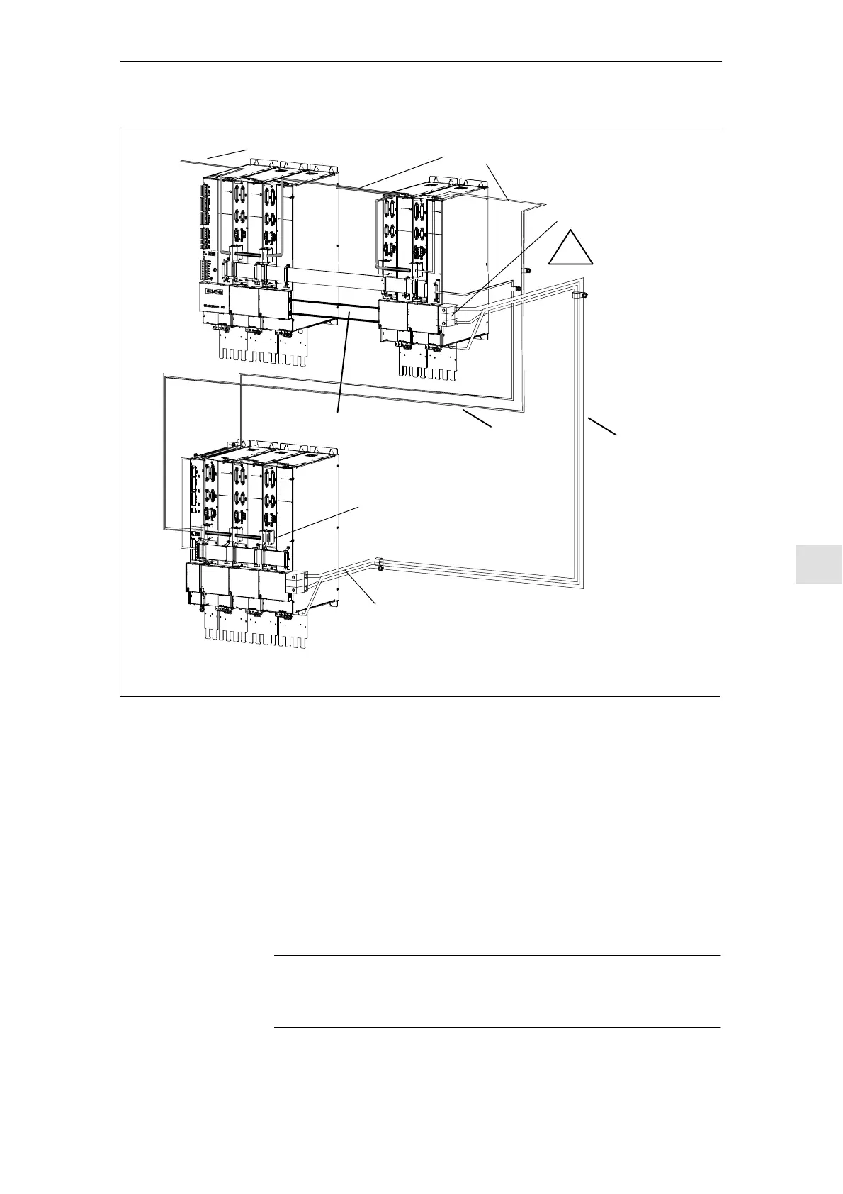
Fig. 9-7 Connection example, two--tier configuration
1. The continuous equipment bus cable of a drive group at one input module or
monitoring module may be a maximum of 2.1 m long (from the supply point).
For a two--tier configuration, two equipment bus branches, each with
max. 2.1 m length from the branching point (supply point) can be used at the
infeed.
2. 1500 mm equipment bus extension for a two--tier configuration with a branch
at the supply/infeed point (Order No.: 6SN1161--1AA00 --0AA1).
3. The drive bus length may not exceed 11 m.
For more than six modules, control units, round cables must be used
instead of ribbon cables.
Note
Connection details for the DC link adapter set, refer to the dimension drawing in
Fig. 12--59.
Data on the
system design
C
ne
De
n
n
MC05.08