2 System Configuration
2
05.01
2.7 Infeed modules
2-63
© Siemens AG 2008 All Rights Reserved
SIMODRIVE 611 Configuration Manual (PJU) – 05/2008 Edition
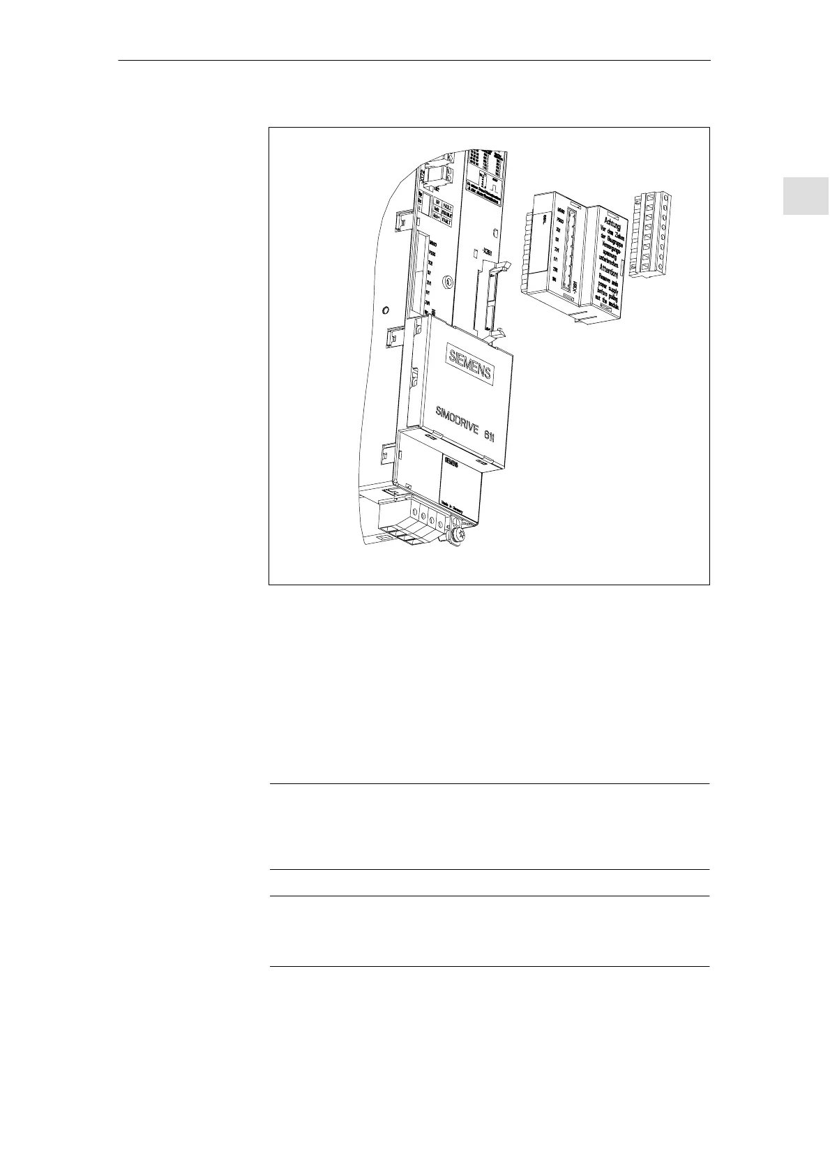
Fig. 2-11 Overvoltage limiter module
If the NE module indicates a line supply fault or if the yellow LED is dark, then
after the line supply and the line fuses have been checked, the overvoltage lim-
iter module should be checked and if required, replaced.
1. Disconnect the equipment from the power source and ensure that it is in a
no–voltage condition.
2. Withdraw the overvoltage limiter module and insert connector X181 onto the
NE module. If the NE module functions correctly, then the overvoltage limiter
module is defective and must be replaced. Otherwise, check the group of
modules.
Note
If an overvoltage limiter module is defective, this results in high overvoltage
peaks/spikes in the line supply. The line supply should be checked as to
whether this is the case.
Notice
If the system is subject to a high–voltage test, the overvoltage limiter modules
must be withdrawn in order to prevent the voltage limiting function responding.
J
Procedure
12.07