3
05.01
3.2 Motor encoder
3-67
© Siemens AG 2008 All Rights Reserved
SIMODRIVE 611 Configuration Manual (PJU) – 05/2008 Edition
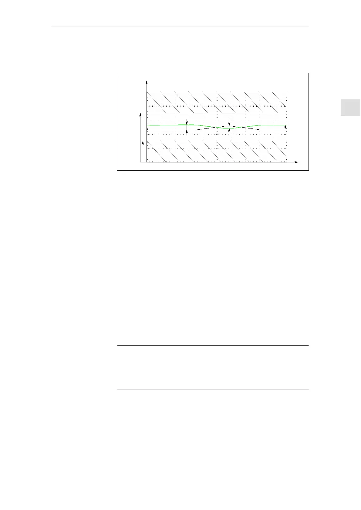
For zero pulse/reference signal R+ and R–
0 V
5 V
Signal
0.2...0.5 V 0.2...0.5 V
3.5 V
1.5 V
t
Fig. 3-2 Signal characteristics for zero pulse/reference signal R+ and R–
If other encoder signals are used or in the case of TTL encoders, encoder sig-
nal monitoring can be triggered. In particular, the lower signal level for reference
signals R+ and R– must be carefully observed.
Key data for resolver as motor encoder:
Pin assignment: in accordance with Chapter 5.2.2, Table 5-13
Number of pole pairs: 1 or equal to the pole–pair count of the motor
Resolver excitation:
the control unit produces the voltage with 4.3 V
RMS
at 9.6 kHz
Nominal input voltage of the controller: sin/cos 2.0 V
RMS
Transmission coefficient of the resolver: approx. 0.46 at 9.6 kHz (often de-
scribed with 1:2 transformation ratio in the datasheets)
The resolver excitation is controlled within the control range to provide the
input voltage of 2.0 V
RMS
.
Maximum excitation current: 28 mA
RMS
(corresponds to the minimum mag-
nitude of 154 Ω of the complex input impedance of the resolver)
Note
The named key data represent starting values for the selection of the resolver
but not a complete specification of the resolver interface. In specific cases, the
user must check whether the chosen resolver in the complete system meets
the requirements.
Resolver
3 Motor Selection, Position/S
eed Sensin
05.08
 Loading...


