Configuration
5.2 Configuring workflow
1FW6 Built-in torque motors
100 Configuration Manual, 07/2017, 6SN1197-0AE00-0BP9
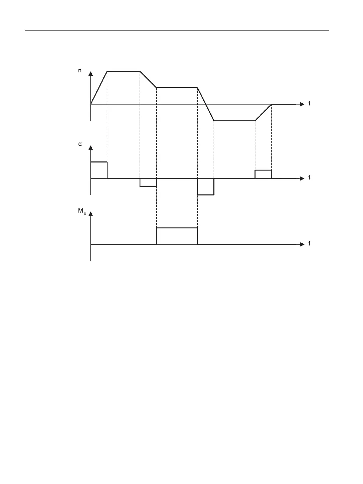
Figure 5-2 Example of a duty cycle with a speed-time diagram n(t), the resulting angular
acceleration-time diagram α(t), and a machining torque-time diagram M
b
(t)
Torque-time diagram
Required motor torque
The required motor torque M
m
is always the sum of the individual torques. The sign in front
of the torque specifications must always be taken into account.
M
m
= M
a
+ M
b
+ M
r
M
a
: Accelerating torque
M
b
: Machining torque
M
r
: Frictional torque

 Loading...


