Electrical connection
8.2 Motor circuit diagram
1FW6 Built-in torque motors
474 Configuration Manual, 07/2017, 6SN1197-0AE00-0BP9
When operated on IT line systems, a protective device should be provided that switches off
the drive system in the case of a ground fault.
In operation with a grounded external conductor, an isolating transformer with grounded
neutral (secondary side) must be connected between the line supply and the drive system.
This protects the winding insulation from excessive stress.
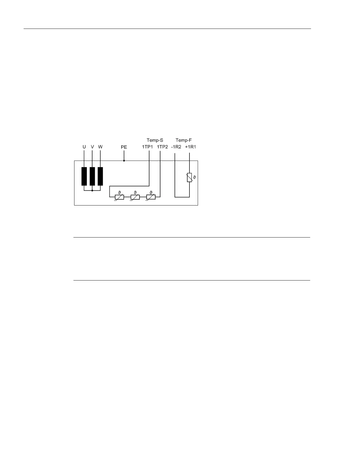
The circuit diagram of a stator looks like this:
Figure 8-1 Circuit diagram of a stator
Note
Additional temperature monitoring circuit Temp-S
1FW6090
-xxxxx-xxx2 to 1FW6290-xxxxx-xxx2 motors are equipped with an additional
temperature monitoring circuit Temp
-S. The associated interface designations are 2TP1 and

 Loading...


