Electrical connection
8.3 System integration
1FW6 Built-in torque motors
512 Configuration Manual, 07/2017, 6SN1197-0AE00-0BP9
Power connection
Connection assignment
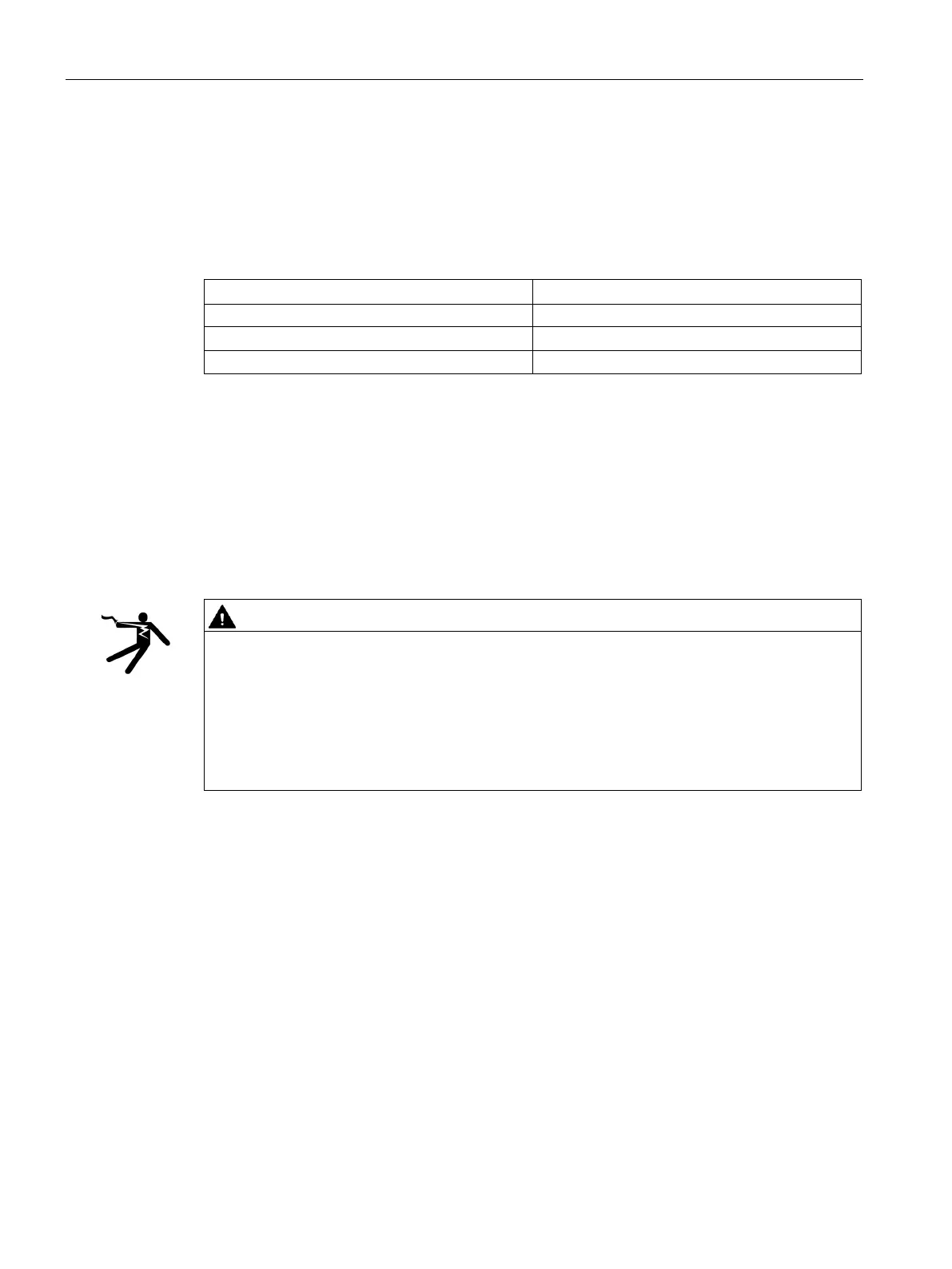
Table 8- 8 Power connection for torque motor
V2 V
For information on connecting the power, also refer to the diagrams relating to "System
integration". The rotor rotates clockwise if the torque motor is connected to phase sequence
U, V, W. See "Defining the direction of rotation (Page 36)".
Signal connection
No direct connection of the temperature monitoring circuits
Risk of electric shock when incorrectly connecting the temperature monitoring circuit
In the case of a fault, circuits Temp-S and Temp-F do not provide safe electrical separation
with respect to the power components.
• Use, for example, the TM120 or the SME12x to connect the Temp-S and Temp-F
temperature monitoring circuits. You therefore comply with the directives for safe
electrical separation according to EN 61800-5-1 (previously safe electrical separation
according to EN 50178).

 Loading...


