1FW6 Built-in torque motors
Configuration Manual, 07/2017, 6SN1197-0AE00-0BP9
519
Installation drawings/Dimension drawings
Installation situation for motors with a cooling jacket
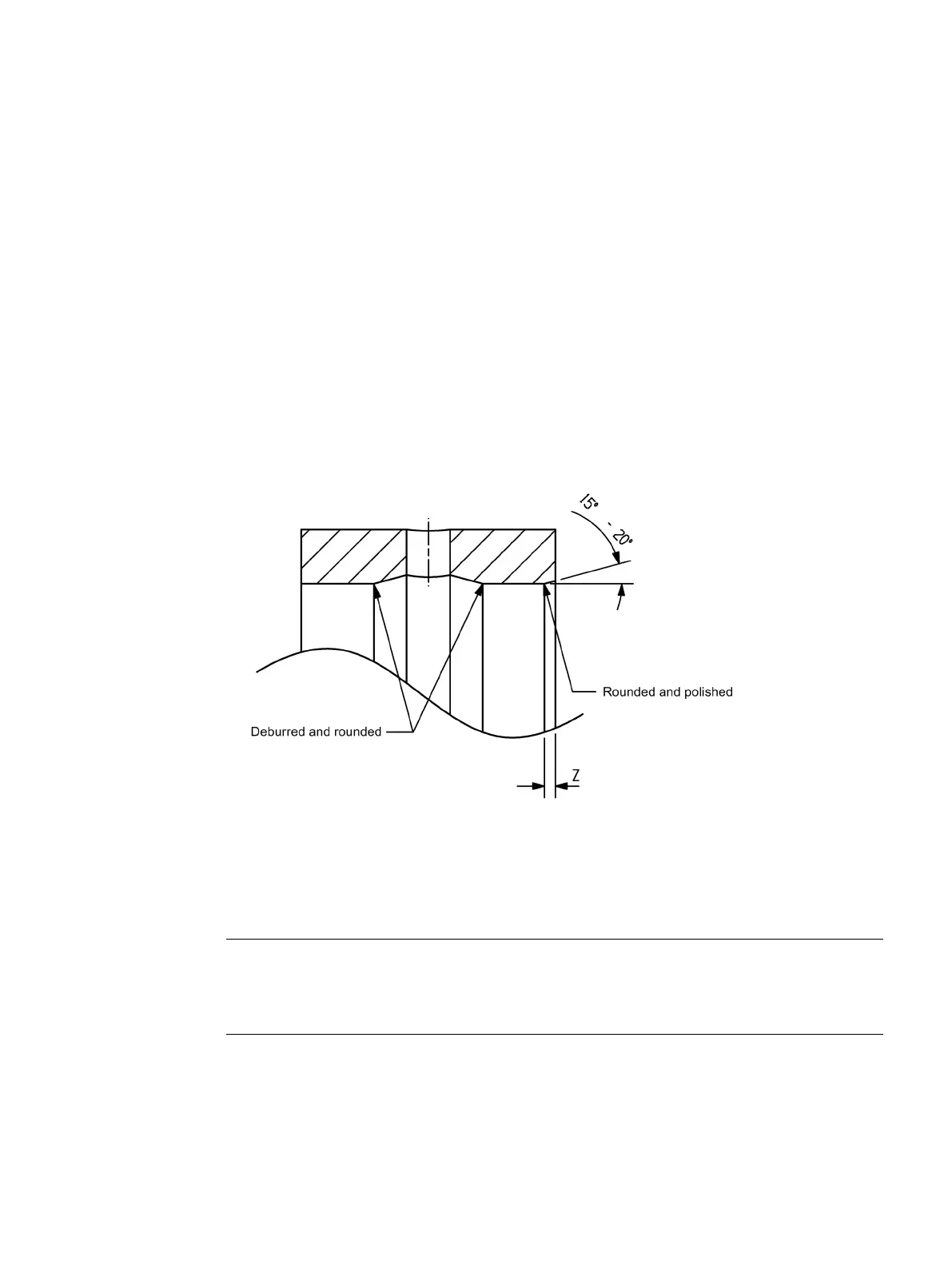
Design information for installation hole and O ring
● Provide insertion inclines: Minimum length Z at 15°: 3 mm, at 20°: 2 mm, edges rounded
and polished
Debur and round inside holes (cooling water connections)
● Surface quality of the opposite sealing surfaces: R
max
≤ 16 µm, R
z
≤ 10 µm, R
a
≤ 1.6 µm
● Note the installation hole fit (H8). If the play is too great, the O-ring does not provide
sufficient sealing or the permissible gap is too large.
Figure 9-1 Design information for installation hole and O ring
Information on the installation drawings
Note
Please note that certain motors can only be mounted at the A flange as a result of their
design, refer to the Table "Mounting at the A flange" in Chapter "Specifications relating to the
m
ounting side (Page 125)".

 Loading...


