EasyManua.ls Logo

Siemens SIMOTICS T-1FW6 - Page 513

Siemens SIMOTICS T-1FW6
560 pages
To Next Page IconTo Next Page
To Previous Page IconTo Previous Page
Loading...
Electrical connection
8.3 System integration
1FW6 Built-in torque motors
Configuration Manual, 07/2017, 6SN1197-0AE00-0BP9
511
Table 8- 6 Pin assignment, Size 1.0 power connector
PIN
Interface
1
U
2
V
PE
PE
4 -
5
-
6
W
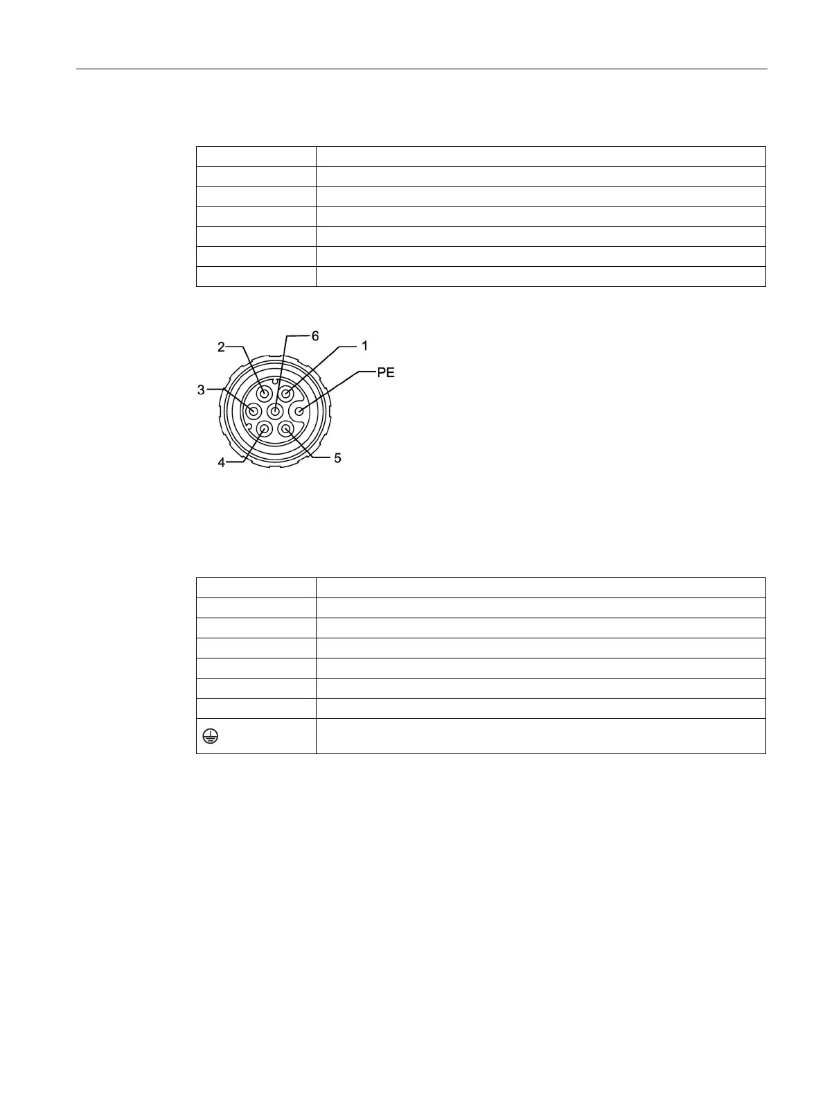
Figure 8-37 Pin configuration, M17 signal connector
Table 8- 7 PIN assignment, M17 signal connector
PIN
Interface
1
-1R2: -KTY or Pt1000
2
+1R1: +KTY or Pt1000
3
1TP1: PTC 130 °C
4
1TP2: PTC 130 °C
5
2TP1: PTC 150 °C *)
6
2TP2: PTC 150 °C *)
PE
*) PTC 150 °C, optional in conjunction with KTY 84

Table of Contents

Other manuals for Siemens SIMOTICS T-1FW6

Related product manuals