EasyManuals Logo

Siemens SIMOTICS T-1FW6 Configuration Manual

Siemens SIMOTICS T-1FW6
560 pages
To Next Page IconTo Next Page
To Previous Page IconTo Previous Page
Page #122 background imageLoading...
Page #122 background image
Configuration
5.4 Installation
1FW6 Built-in torque motors
120 Configuration Manual, 07/2017, 6SN1197-0AE00-0BP9
Radial forces between the stator and rotor
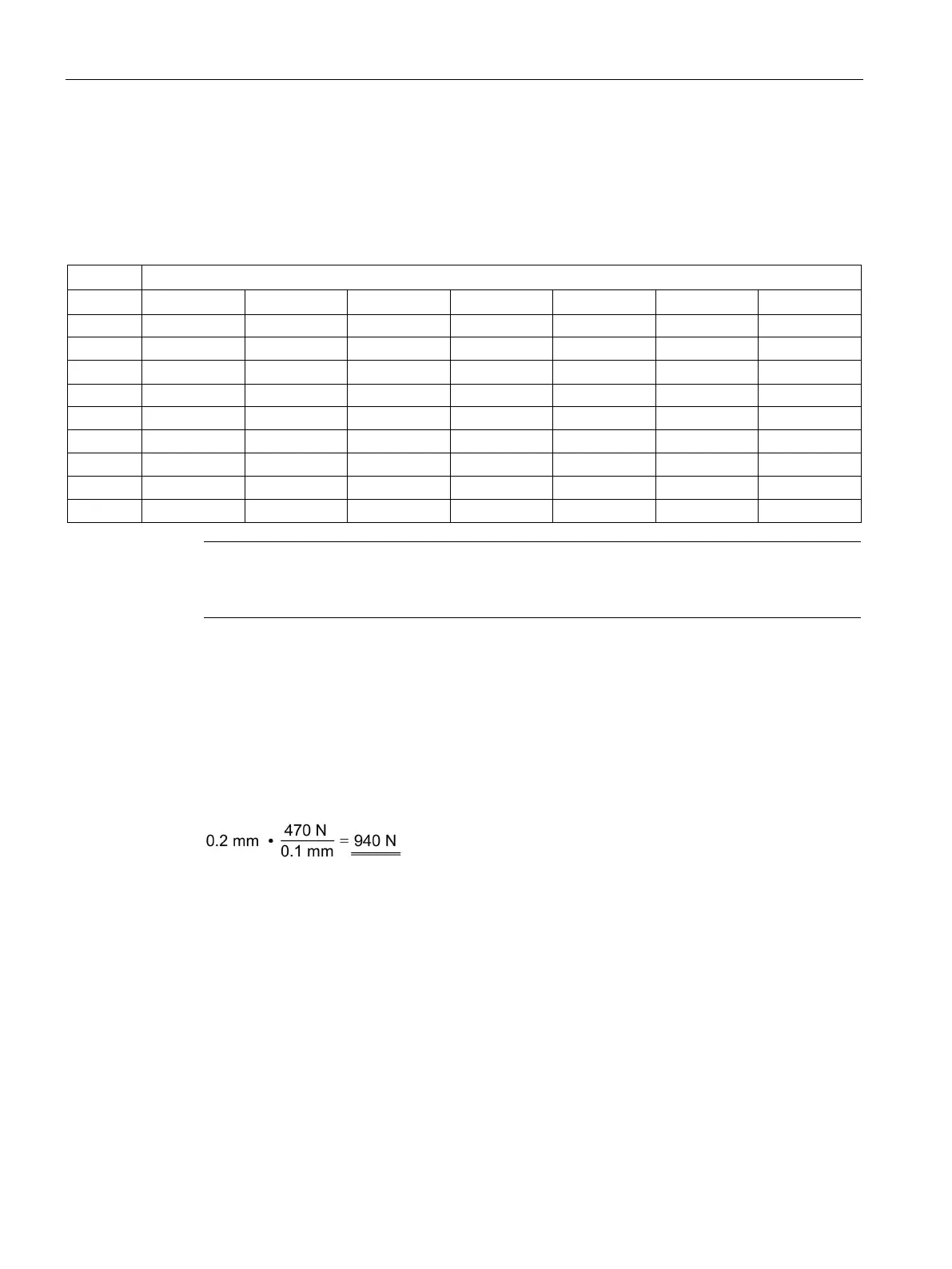
The following table shows the active radial forces (in N per 0.1 mm centering error) between
the stator and rotor. The longer the active component, the greater the radial force.
Table 5- 3 Radial forces in N/0.1 mm with radial centering errors during installation
Active length in mm
30
50
70
100
110
150
200
1FW605
80
140
190
270
-
400
-
1FW606
110
180
250
350
-
520
-
1FW609 - 240 330 470 - 710 -
1FW613
-
360
500
710
-
1070
-
1FW615 - 330 460 660 - 990 -
1FW616
-
290
410
590
-
880
1180
1FW619
-
350
490
710
-
1060
1410
1FW623
-
420
590
840
-
1260
1680
1FW629
-
-
600
-
940
1280
1630
Note
You must note the radial forces between the stator and rotor as well as the maximum
permissible concentricity error specified in the dimension drawings.
Example
With torque motor 1FW6090-0Px010-xxxx (active component length: 100 mm), the
eccentricity is 0.2 mm, for example.
The active radial force as a result of this centering error is, therefore:

Table of Contents

Other manuals for Siemens SIMOTICS T-1FW6

Questions and Answers:

Question and Answer IconNeed help?

Do you have a question about the Siemens SIMOTICS T-1FW6 and is the answer not in the manual?

Siemens SIMOTICS T-1FW6 Specifications

General IconGeneral
BrandSiemens
ModelSIMOTICS T-1FW6
CategoryEngine
LanguageEnglish

Related product manuals