Coupled motors
10.3 Machine design and adjustment of the phase angle
1FW6 Built-in torque motors
542 Configuration Manual, 07/2017, 6SN1197-0AE00-0BP9
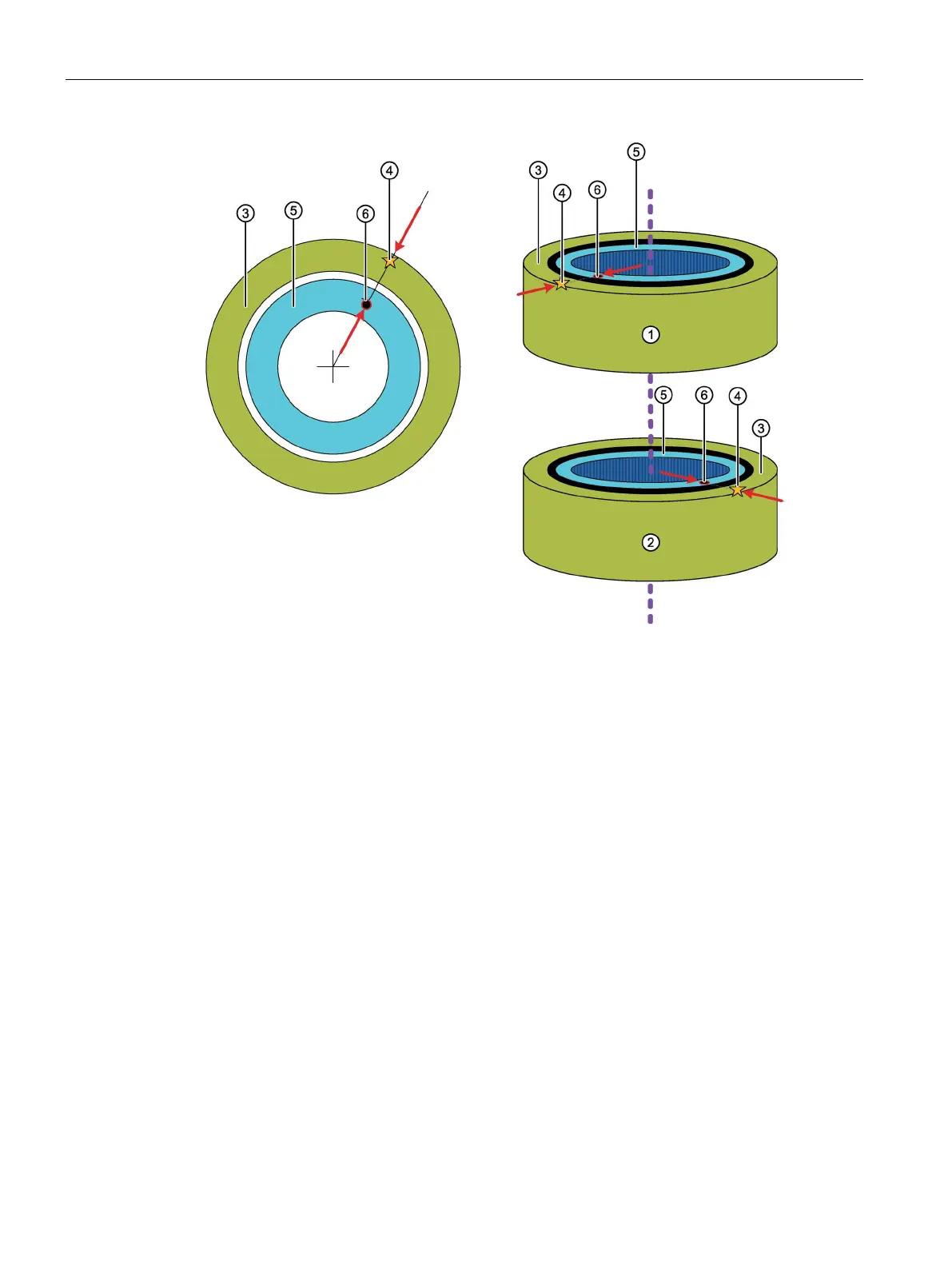
Reference mark at the stator (various forms depending on the motor)
Reference mark at the rotor
Figure 10-1 Reference marks for 1FW6 built-in torque motors (schematic)
The phase angles have been correctly adjusted if the following state is reached while the
axis is rotating in operation:
The reference marks of all rotors are always aligned at the same point in time with the
reference mark of the associated stator.
The machine design must ensure that this applies. You can achieve the required mechanical
adjustability of the mounting position, e.g. using an intermediate flange with elongated holes.
The angular tolerance is +/-1° mechanical.
The stator reference marks do not have to align with one another.
The rotor reference marks do not have to align with one another.
 Loading...


