Mechanical properties
3.1 Cooling
1FW6 Built-in torque motors
Configuration Manual, 07/2017, 6SN1197-0AE00-0BP9
57
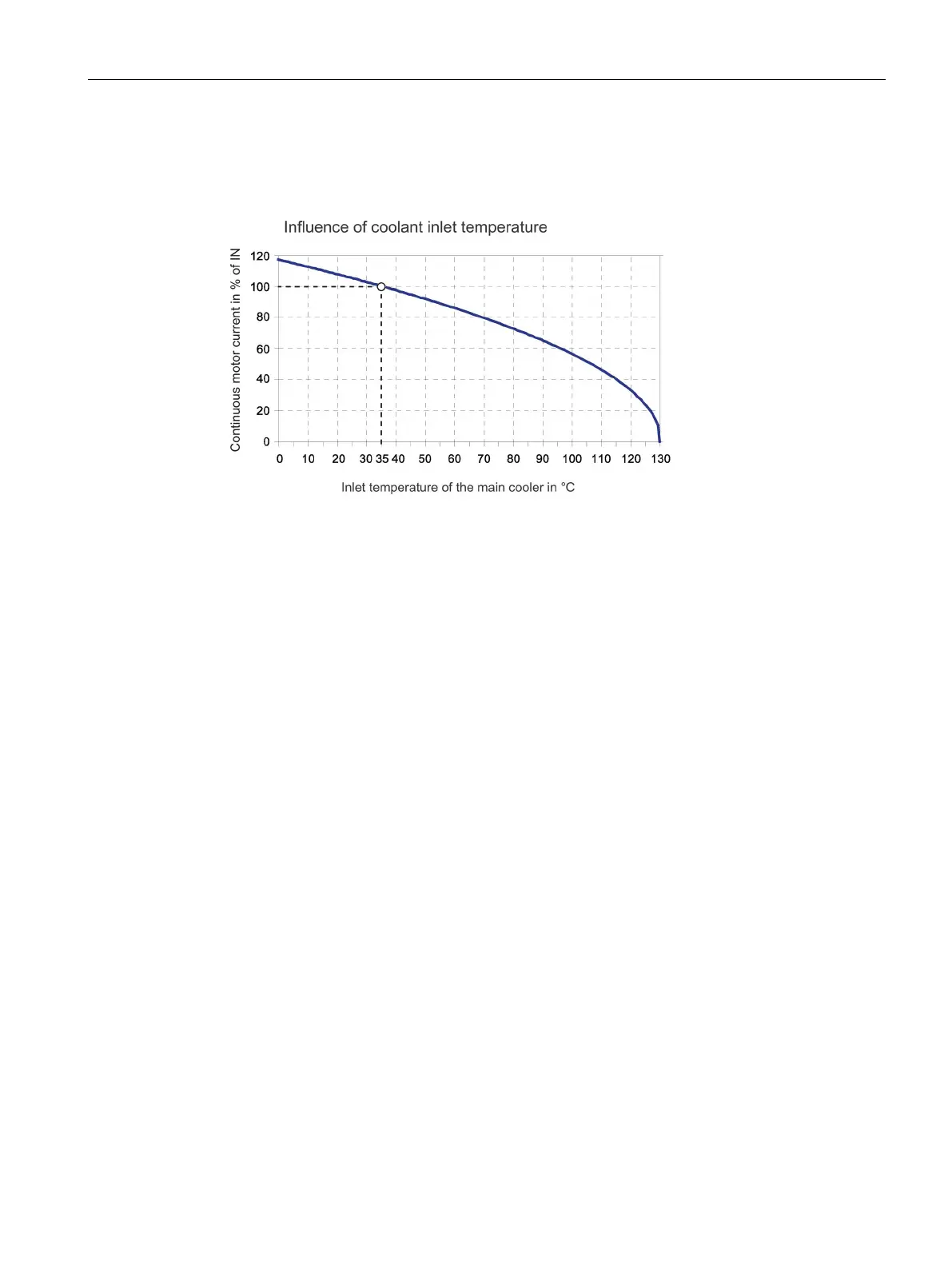
The following diagram shows the principle dependency of the relevant continuous motor
current on the intake temperature of the cooling water in the main cooler The rotor losses are
omitted as negligible.
Figure 3-1 Influence of the coolant inlet temperature
Use a heat-exchanger unit to ensure an inlet temperature of 35 °C. More than one motor can
be operated on a single heat-exchanger unit. The heat-exchanger units are not included in
the scope of supply.
The cooling power is calculated from the sum of the power losses of the connected motors.
Adapt the pump power to the specified flow and pressure loss of the cooling circuit.
For a list of companies from whom you can obtain heat exchanger units, see the appendix.
Dimensioning the heat-exchanger unit
The power loss generated in the motor during continuous operation causes a thermal flow to
take place. The surrounding machine assembly dissipates a small percentage of this thermal
flow. The cooling system coolant dissipates the majority of this thermal flow. The cooling
system must dissipate 85 % to 90 % of the power loss that occurs. Appropriately dimension
the cooling system rating.
If you operate several motors simultaneously on one cooling system, then the cooling
system must be able to dissipate the sum of the individual power losses.
In continuous operation, only load the motor so that the continuous rms torque of the duty
cycle M
eff
does not exceed the rated torque M
N
. In continuous operation, it is not permissible
for the operating point in the M-n diagram to be above the characteristic for S1 duty. As a
consequence, the maximum rms power loss P
V
only reaches the rated power loss P
V,N
.

 Loading...


