3. Screw the connection jumper firmly in place using the supplied M5 nuts with a torque of 3
Nm.
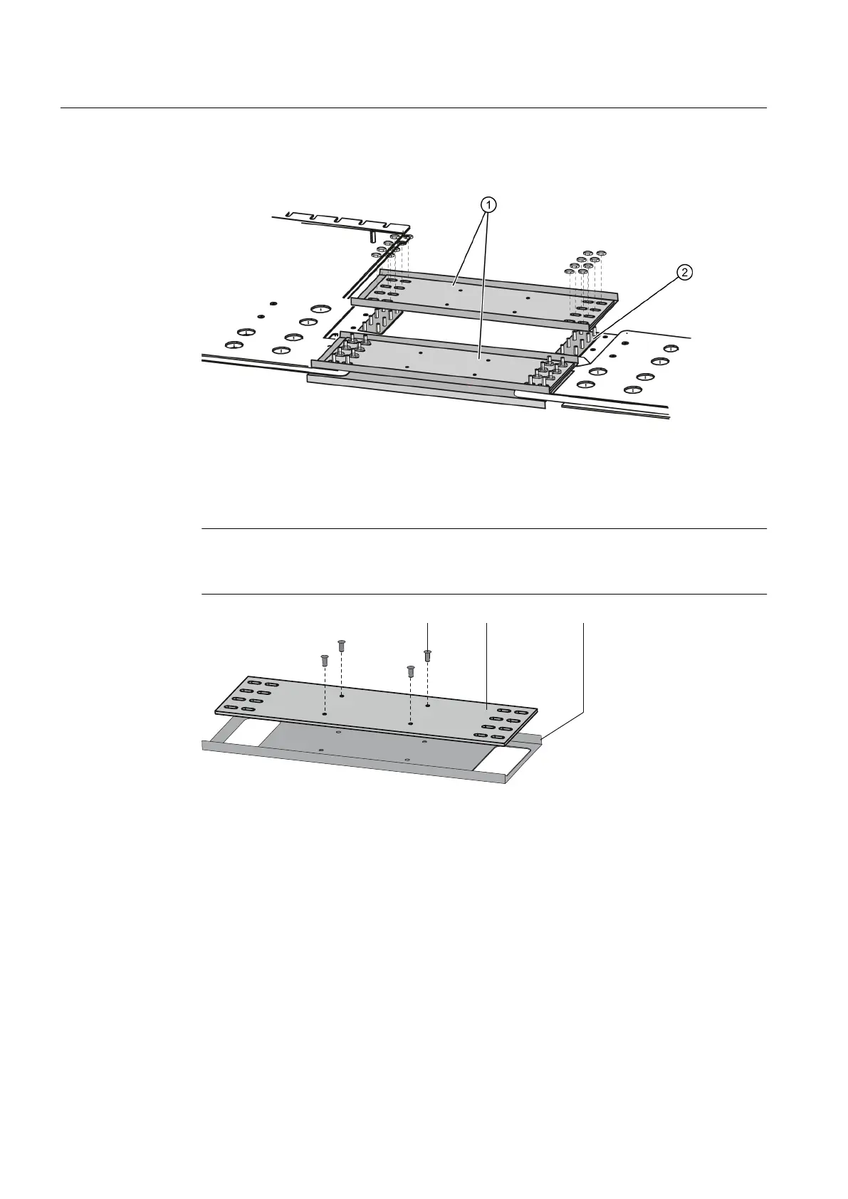
① Connection jumper
② Copper spacer plate
Figure 5-4 DC-bus connection
4. Mount the connection jumpers on the bottom of the DC bus in exactly the same way.
Note
In exceptional cases the connection jumpers are not shipped in the assembled state.
Assemble them as shown in the diagram "Assembling the DC bus connection".
① Insulating plate
② Busbar
③ Rivets (not supplied)
Figure 5-5 Assembling the DC-bus connection
5.8 Connecting the interface terminals
Connecting the interface terminals of several cabinets
If several cabinets are set up as one unit, the interface terminals of the cabinets must be
connected with each other.
Installation
5.8 Connecting the interface terminals
SINAMICS GM150 6SL3815-2LN41-4AA2
92 Operating Instructions 04/2017

 Loading...


