Programming and Operating Manual (Milling)
146 6FC5398-4DP10-0BA6, 09/2017
The following example is suitable for testing the parameterization of the TRACYL cylinder transformation:
Cutting edge position (Only for turning tools)
Length offset vector (Calculation acc. to t ype and plane)
Slot width b for slotting saw, roundin g radius for milling tools
Projection k (For slotting saw only)
Angle for taper milling tools
Length and radius compensation
Remaining parameters to $TC_DP24=0 (To ol base dimension/adapter)
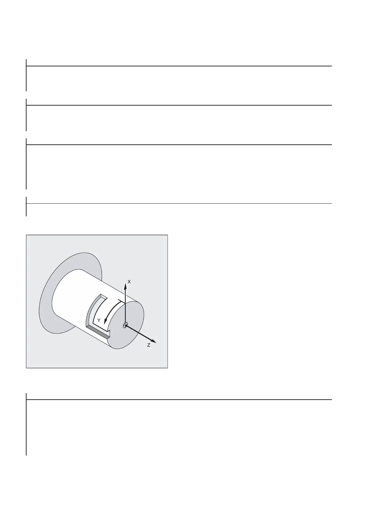
Example: Making a hook-shaped groove
Activate cylinder surface transformation:
Required tool: T1 milling tool, radius=3 mm, edge position=8
N10 T1 D1 G54 G90 G94
F1000
; Tool selection, clamping compensatio n
; Approach the starting position
; Set the second spindle as the main s pindle
; Change the diameter dimensio nin g to radius dimensioning
; Activate cylinder surface ;transform ation

 Loading...


