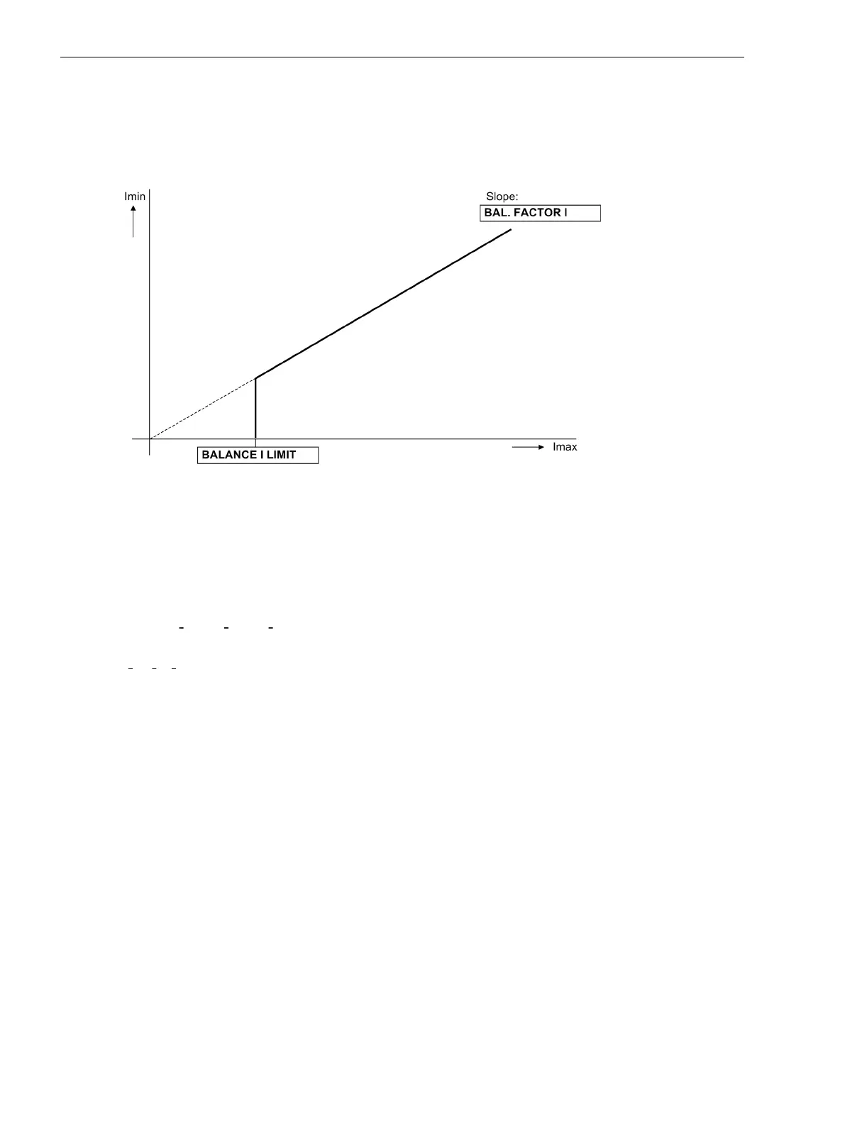
Thereby Ιmax is the largest of the three phase currents and Imin the smallest. The symmetry factor BAL.
FACTOR I (address 8105) represents the allowable asymmetry of the phase currents while the limit value
BALANCE I LIMIT (address 8104) is the lower limit of the operating range of this monitoring (see
Figure 2-45). Both parameters can be set. The dropout ratio is about 97 %.
This fault is signalled after settable delay time with
Fail I balance
.
[stromsymmetrieueberwachung-020313-kn, 1, en_US]
Figure 2-45 Current symmetry monitoring
Phase Sequence
To detect swapped phase connections in the current input circuits, the direction of rotation of the phase
currents is checked. Therefore the sequence of the zero crossings of the currents (having the same sign) is
checked.
The default setting assumes a positive phase sequence.
Currents:
Ι
A
leads Ι
B
leads Ι
C
Supervision of current rotation requires a maximum current of
|
Ι
A
|, |Ι
B
|, Ι
C
| > 0.5 Ι
Nom
.
For abnormal phase sequence, the message
Fail Ph. Seq. I
is issued.
For applications in which an opposite phase sequence is expected, the protective relay should be adjusted via
a binary input or the respective parameter PHASE SEQ. (address 209). If the phase sequence is changed in
the device, phases B and C internal to the relay are reversed, and the positive and negative sequence currents
are thereby exchanged (see also Section 2.15.2 Setting Notes). The phase-related messages, malfunction
values, and measured values are not affected by this.
Setting Notes
Measured Value Monitoring
The sensitivity of measured value monitor can be modified. Default values which are sufficient in most cases
are preset. If especially high operating asymmetries in the currents are to be expected during operation, or if it
becomes apparent during operation that certain monitoring functions activate sporadically, then the setting
should be less sensitive.
Address 8104 BALANCE I LIMIT determines the limit current above which the current symmetry monitor is
effective. Address 8105 BAL. FACTOR I is the associated symmetry factor; that is, the slope of the
symmetry characteristic curve. In address 8111 T BAL. I LIMIT you set the delay time for fault message
no. 163
Fail I balance
.
2.8.1.5
Functions
2.8 Monitoring Functions
124 SIPROTEC 4, 7SJ61, Manual
C53000-G1140-C210-6, Edition 05.2016

 Loading...


