Pre-defined CFC Charts
Some CFC charts are already installed upon delivery of the SIPROTEC 4 device:
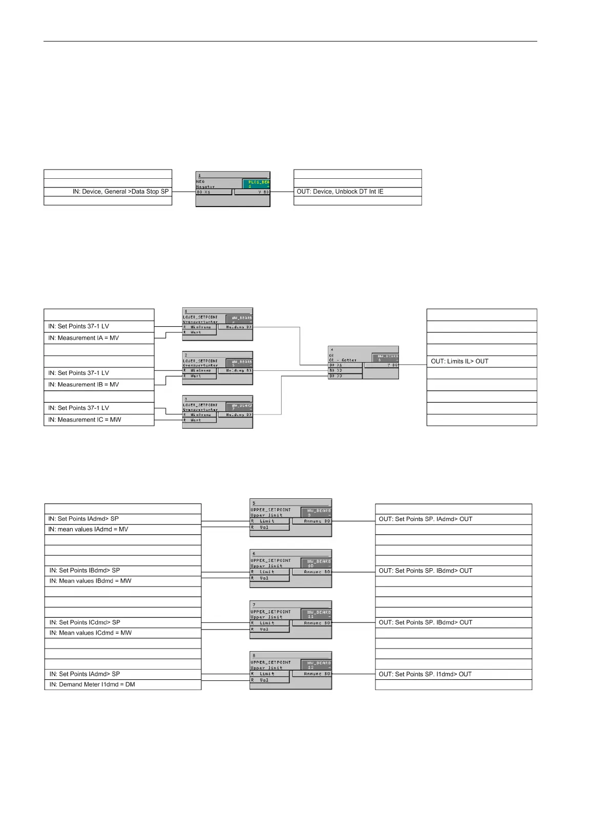
Device and System Logic
The NEGATOR block assigns the input signal "DataStop" directly to an output. This is not directly possible
without the interconnection of this block.
[cfc-mm-sperre-211002-kn, 1, en_US]
Figure E-5 Logical Link between Input and Output
Set points MV
Using modules on the running sequence ”measured value processing", a low current monitor for the three
phase currents is implemented. The output message is set high as soon as one of the three phase currents falls
below the set threshold:
[cfc-unterstromueberwachung-020313-kn, 1, en_US]
Figure E-6 Undercurrent monitoring
Using modules on the running sequence ”measured value processing", an additional overcurrent monitor is
implemented.
[cfc-ueberstromueberwachung-020313-kn, 1, en_US]
Figure E-7 Overcurrent monitoring
E.6
Default Settings and Protocol-dependent Functions
E.6 Pre-defined CFC Charts
380 SIPROTEC 4, 7SJ61, Manual
C53000-G1140-C210-6, Edition 05.2016

 Loading...


