[front-geh-einhalb-o-frontkap-7sj61-20121112, 1, en_US]
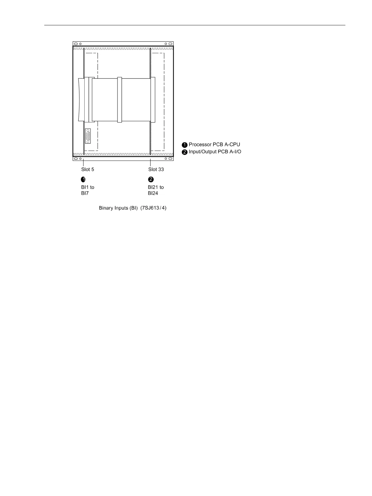
Figure 3-4
Front view of housing size
1
/
2
after removal of the front cover (simplified and scaled down)
Switch elements on the PCBs
Three different releases of the A–CPU board are available. They are shown in the following figures. The loca-
tion of the miniature fuse (F1) and of the buffer battery (G1) are also shown in the following figures.
3.1.2.3
Mounting and Commissioning
3.1 Mounting and Connections
SIPROTEC 4, 7SJ61, Manual 239
C53000-G1140-C210-6, Edition 05.2016

 Loading...


