[montage-gehaeuse-grafikdisplay-halb-st-040403, 1, en_US]
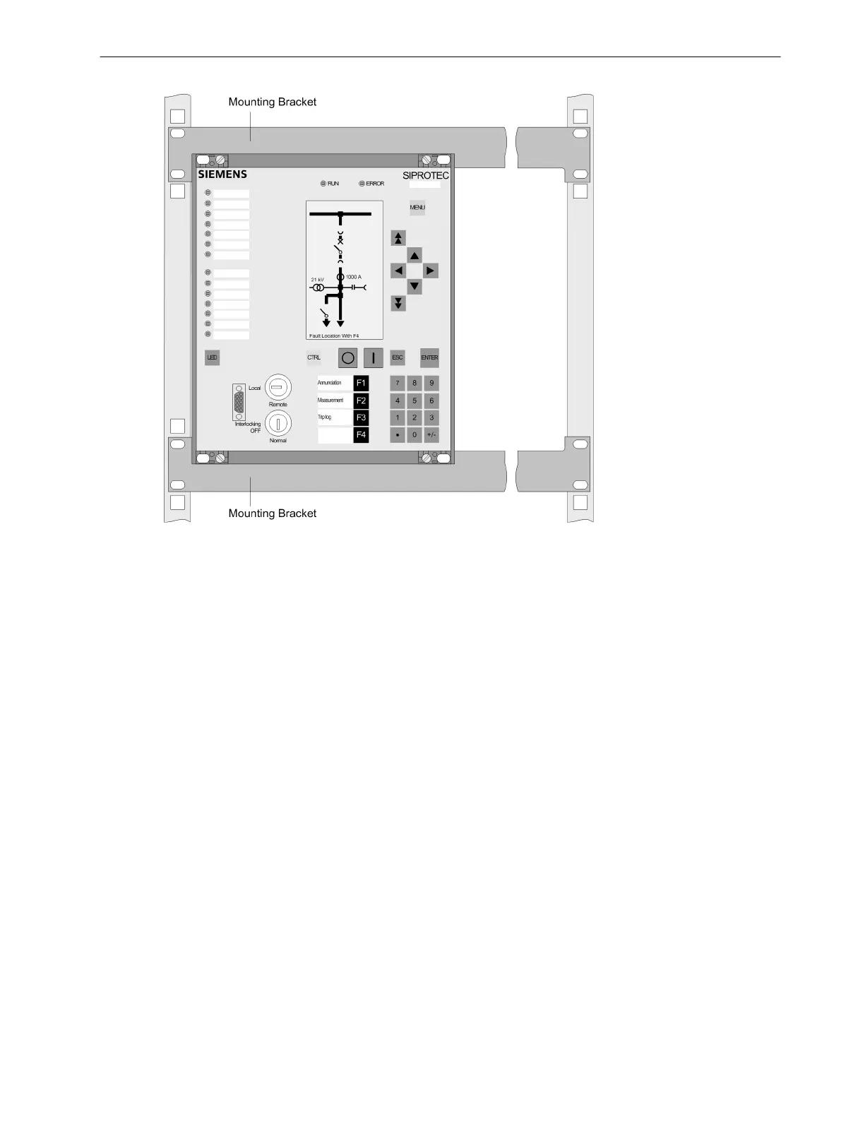
Figure 3-20
Installing a device in a rack or cubicle (housing size
1
/
2
)
Panel Flush Mounting
For installation proceed as follows:
•
Secure the device to the panel with 4 screws. For dimensions see the Technical Data, Section4.22 Dimen-
sions.
•
Connect the robust low-ohmic protective ground or station ground to the grounding terminal on the rear
plate of the device. The cross-sectional area of the cable used must correspond to the maximum
connected crosssection, but must be at least 2.5
2
.
•
Alternatively, fasten the said ground to the grounding surface on the side with at least one M4 screw.
•
Connections according to the circuit diagram via screw terminals, connections for optical fiber cable and
electrical communication modules via the housings. The SIPROTEC 4 System Description provides infor-
mation regarding maximum wire size, torque, bending radius and cable relief and must be observed.
3.1.3.3
Mounting and Commissioning
3.1 Mounting and Connections
SIPROTEC 4, 7SJ61, Manual 259
C53000-G1140-C210-6, Edition 05.2016

 Loading...


