The actual storage time begins at the pre-fault time PRE. TRIG. TIME (address 404) ahead of the reference
instant, and ends at the post-fault time POST REC. TIME (address 405) after the storage criterion has reset.
The maximum storage duration of each fault record (MAX. LENGTH) is entered at address 403. Recording per
fault must not exceed 5 seconds. At least 8 records can be saved altogether with a minimum total time of
20 s .
An oscillographic record can be triggered by a status change of a binary input, or from a PC via the operator
interface. Storage is then triggered dynamically. The length of the fault recording is set in address 406 BinIn
CAPT.TIME (but not longer than MAX. LENGTH, address 403). Pre-fault and post-fault times will add to this.
If the binary input time is set to ∞, the length of the record equals the time that the binary input is activated
(static), but not longer than the MAX. LENGTH (address 403).
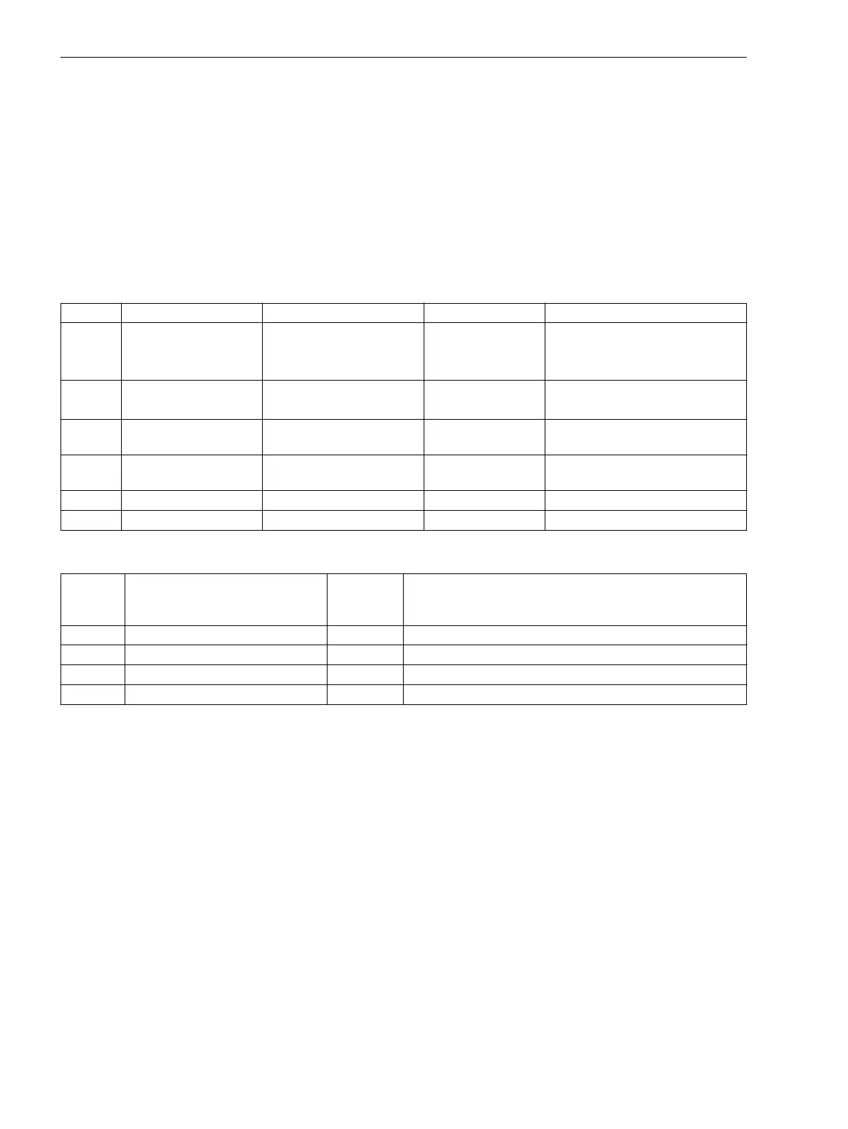
Settings
Addr. Parameter Setting Options Default Setting Comments
401 WAVEFORMTRIGGER Save w. Pickup
Save w. TRIP
Start w. TRIP
Save w. Pickup Waveform Capture
402 WAVEFORM DATA Fault event
Pow.Sys.Flt.
Fault event Scope of Waveform Data
403 MAX. LENGTH 0.30 .. 5.00 sec 2.00 sec Max. length of a Waveform
Capture Record
404 PRE. TRIG. TIME 0.05 .. 0.50 sec 0.25 sec Captured Waveform Prior to
Trigger
405 POST REC. TIME 0.05 .. 0.50 sec 0.10 sec Captured Waveform after Event
406 BinIn CAPT.TIME 0.10 .. 5.00 sec; ∞ 0.50 sec Capture Time via Binary Input
Information List
No.
Information Type of
Informa-
tion
Comments
- FltRecSta IntSP Fault Recording Start
4 >Trig.Wave.Cap. SP >Trigger Waveform Capture
203 Wave. deleted OUT_Ev Waveform data deleted
30053 Fault rec. run. OUT Fault recording is running
Settings Groups
Up to four different setting groups can be created for establishing the device's function settings.
Applications
•
Setting groups enable the user to save the corresponding settings for each application so that they can
be quickly called up when required. All setting groups are stored in the device. Only one setting group
may be active at a time.
Description
Changing Setting Groups
During operation the user can switch back and forth setting groups locally, via the operator panel, binary
inputs (if so configured), the service interface using a personal computer, or via the system interface. For
reasons of safety it is not possible to change between setting groups during a power system fault.
A setting group includes the setting values for all functions that have been selected as Enabled during
configuration (see Section 2.1.1.2 Setting Notes). In 7SJ61 relays, four independent setting groups (A to D)
are available. While setting values may vary, the selected functions of each setting group remain the same.
2.1.4.3
2.1.4.4
2.1.5
2.1.5.1
Functions
2.1 General
42 SIPROTEC 4, 7SJ61, Manual
C53000-G1140-C210-6, Edition 05.2016

 Loading...


