Connector Assignment
On the Ports
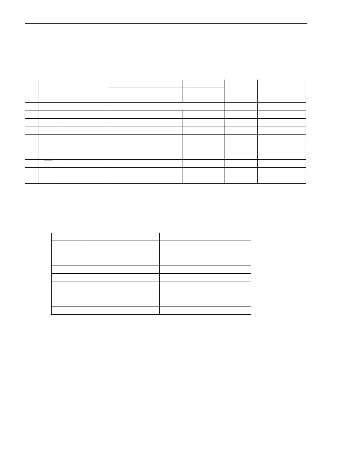
Table B-1 Connector Assignment
Pin-
Nr.
RS232 RS485 Profibus FMS Slave, RS485 Modbus RS485 EN 100
elektr.
RJ45
IEC 60870–5–103
redundant
RS485 (RJ45)
Profibus DP Slave, RS485 DNP 3.0 RS485
1 Shield (electrically connected with shield end) Tx+ B/B’ (RxD/TxD-P)
2 RxD – – – Tx– A/A’ (RxD/TxD-N)
3 TxD A/A’ (RxD/TxD-N) B/B’ (RxD/TxD-P) A Rx+
4 – – CNTR-A (TTL) RTS (TTL Pegel) –
5 GND C/C’ (GND) C/C’ (GND) GND1 –
6 – – +5 V (max. load <100 mA) VCC1 Rx–
7 RTS
–
1)
– – –
8 CTS B/B’ (RxD/TxD-P) A/A’ (RxD/TxD-N) B –
9 – – – – nicht
vorhanden
1)
Pin 7 also carries the RTS signal with RS232 level when operated as RS485-Schnittstelle interface. Pin 7 must
therefor not be connected!
Time Synchronization Port
Table B-2
Assignment DSUB connetors of the Time Synchronization Port
Pin-No. Designation Signal Meaning
1 P24_TSIG Input 24 V
2 P5_TSIG Input 5 V
3 M_TSIG Return Line
4
–
1)
–
1)
5 Screen Screen Potential
6 – –
7 P12_TSIG Input 12 V
8
P_TSYNC
1)
Input 24 V
1)
9 Screen Screen Potential
1)
assigned, but not available
B.4
Terminal Assignments
B.4 Connector Assignment
360 SIPROTEC 4, 7SJ61, Manual
C53000-G1140-C210-6, Edition 05.2016

 Loading...


