Termination
Busbar capable interfaces always require a termination at the last device to the bus, i.e. terminating resistors
must be connected. On the 7SJ61 device, this applies to variants with RS485 or PROFIBUS interfaces.
The terminating resistors are located on the RS485 or Profibus interface module mounted on the processor
input/output board CPU (serial no. 1 in Figure 3-3 and Figure 3-4).
With default setting the jumpers are set such that the terminating resistors are disconnected. Both jumpers of
a board must always be plugged in the same way.
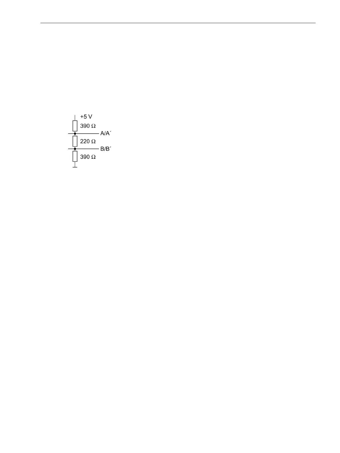
The terminating resistors can also be connected externally (e.g. to the connection module), see Figure 3-16. In
this case, the terminating resistors located on the RS485 or Profibus interface module or directly on the PCB of
the processor module CPU must be switched OFF.
[externe-terminierung-020313-kn, 1, en_US]
Figure 3-16 Termination of the RS485 interface (external)
Reassembly
The device is assembled in the following steps:
•
Carefully insert the boards into the case. The mounting locations are shown in Figure 3-3 and Figure 3-4.
For the model of the device designed for surface mounting, use the metal lever to insert the processor
circuit board A-CPU. The installation is easier with the lever.
•
First, plug the plug connector of the ribbon cable onto the input/output board I/O and then onto the A-
CPU processor board. Do not bend any connector pins! Do not use force!
•
Insert the plug connector of the ribbon cable between the processor board A-CPU and the front cover in
the socket on the front cover.
•
Press the latches of the plug connectors together.
•
Replace the front cover and secure to the housing with the screws.
•
Mount the covers again.
•
Re-fasten the interfaces on the rear of the device housing. This activity is not necessary if the device is
designed for surface mounting.
Installation
Panel Flush Mounting
For installation proceed as follows:
•
Remove the 4 covers on the corners of the front plate. Thus, 4 elongated holes are revealed in the
mounting bracket and can be accessed.
•
Insert the device into the panel cut-out and fasten it with 4screws. For dimensions refer to Section
4.22 Dimensions.
•
Put the 4 covers back in place.
3.1.2.5
3.1.3
3.1.3.1
Mounting and Commissioning
3.1 Mounting and Connections
SIPROTEC 4, 7SJ61, Manual 255
C53000-G1140-C210-6, Edition 05.2016

 Loading...


