Functions
2.8 Undervoltage and Overvoltage Protection 27/59 (Optional)
SIPROTEC, 7SD80, Manual
E50417-G1140-C474-A1, Release date 09.2011
118
Overvoltage Positive Sequence System V
1
The device calculates the positive sequence system according to its defining equation
V
1
=
1
/
3
·(V
A
+ a·V
B
+ a
2
·V
C
)
where a = e
j120°
.
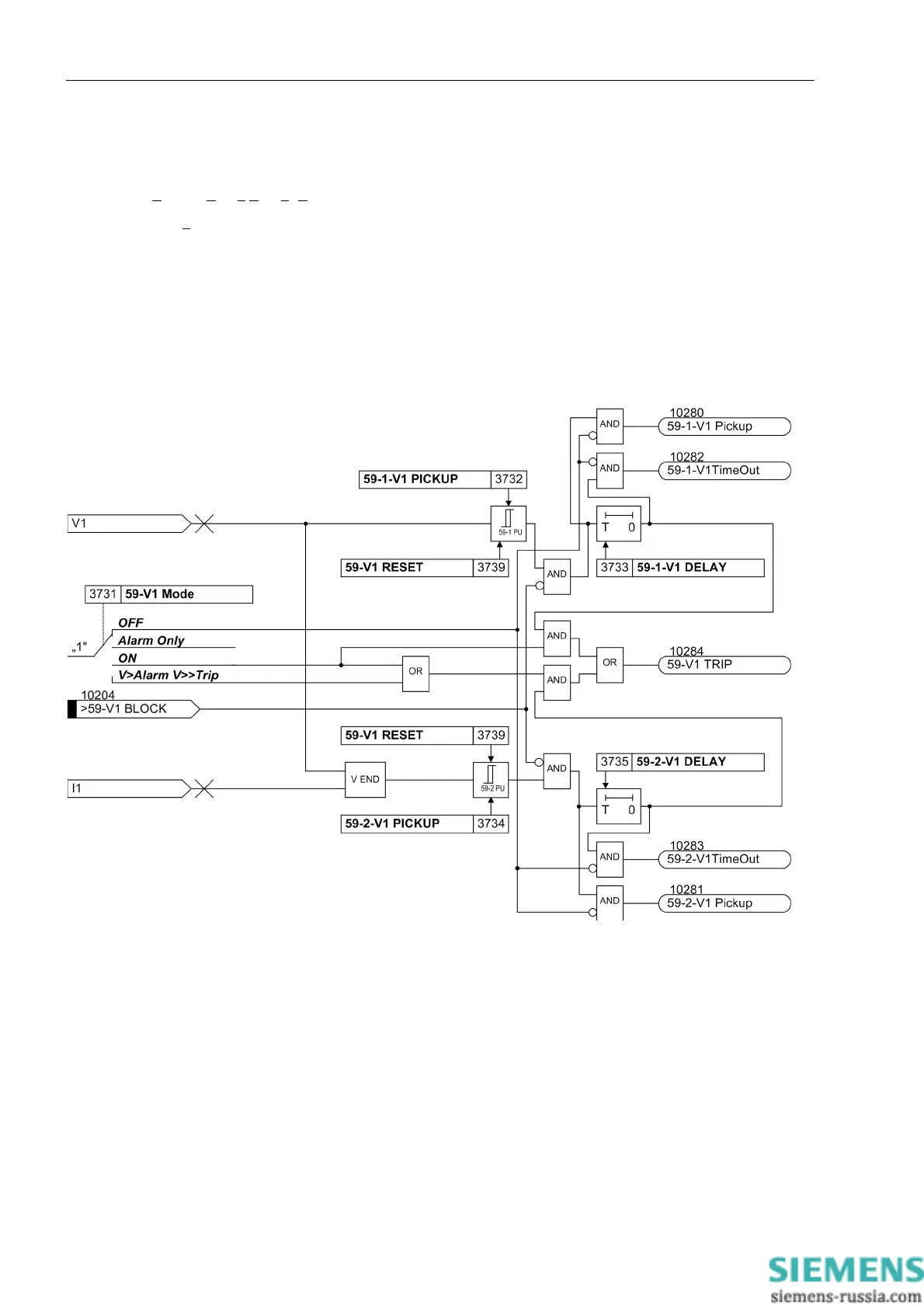
The resulting positive sequence voltage is fed to the two threshold elements 59-1-V1 PICKUP (address
3732) and 59-2-V1 PICKUP (address 3734) (see Figure 2-47). Combined with the associated time delays
59-1-V1 DELAY (address 3733) and 59-2-V1 DELAY (address 3735) these elements form a two-element
overvoltage protection for the positive sequence system. Here too, the dropout ratio can be set.
The overvoltage protection for the positive sequence system can also be blocked via a binary input „>59-V1
BLOCK“.
Figure 2-47 Logic diagram of the overvoltage protection for the positive sequence voltage system

 Loading...


