Functions
2.8 Undervoltage and Overvoltage Protection 27/59 (Optional)
SIPROTEC, 7SD80, Manual
E50417-G1140-C474-A1, Release date 09.2011
119
Overvoltage Negative Sequence System V
2
The device calculates the negative sequence system voltages according to its defining equation:
V
2
=
1
/
3
·(V
A
+ a
2
·V
B
+ a·V
C
)
where a = e
j120°
.
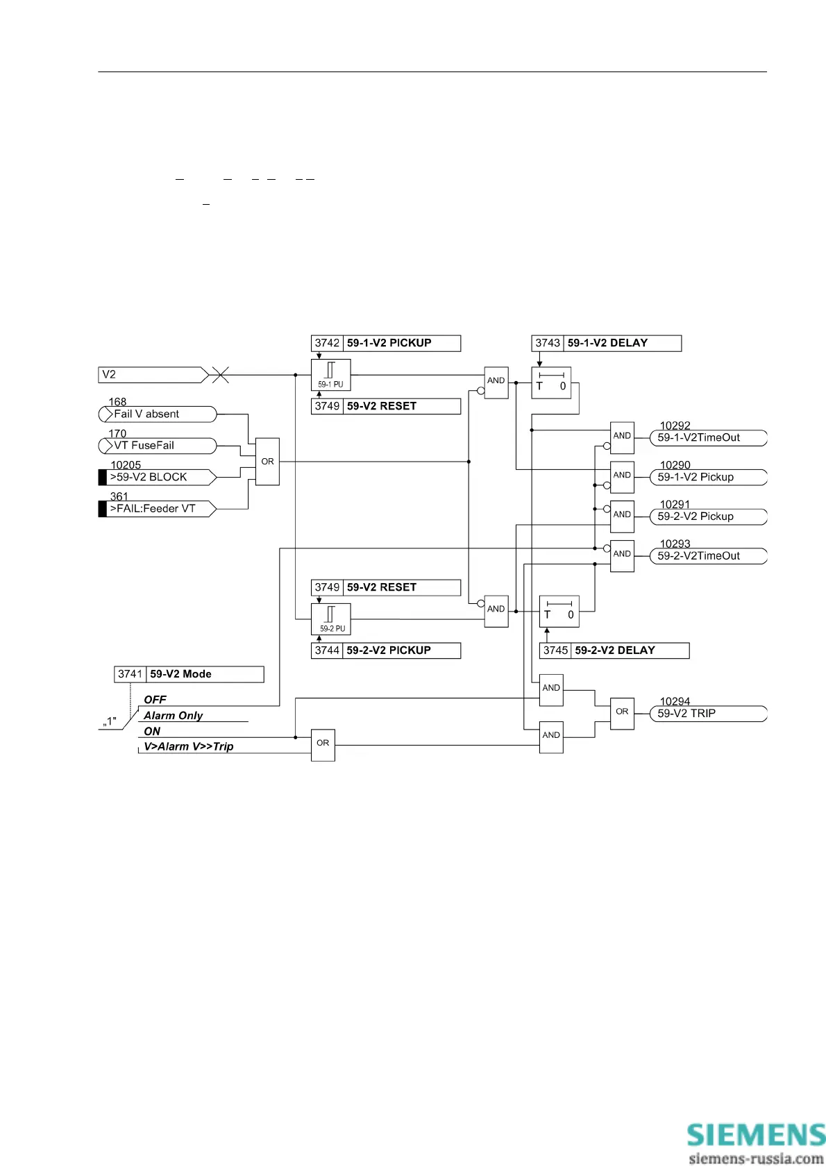
The resulting negative sequence voltage is fed to the two threshold elements 59-1-V2 PICKUP (address
3742) and 59-2-V2 PICKUP (address 3744). Figure 2-48 shows the logic diagram. Combined with the as-
sociated time delays 59-1-V2 DELAY (address 3743) and 59-2-V2 DELAY (address 3745) these elements
form a two-element overvoltage protection for the negative sequence system. Here too, the dropout ratio can
be set.
Figure 2-48 Logic diagram of the overvoltage protection for the negative sequence voltage system V
2
The overvoltage protection for the negative sequence system can also be blocked via a binary input „>59-V2
BLOCK“. The elements of the negative sequence voltage protection are automatically blocked as soon as an
asymmetrical voltage failure is detected („fuse failure monitor“, also see Section 2.14.1, margin heading Rapid
Measuring Voltage Failure „Fuse-Failure-Monitor“) or when tripping of the MCB for voltage transformers has
been signaled via the binary input „>FAIL:Feeder VT“ (internal indication „internal blocking“).

 Loading...


