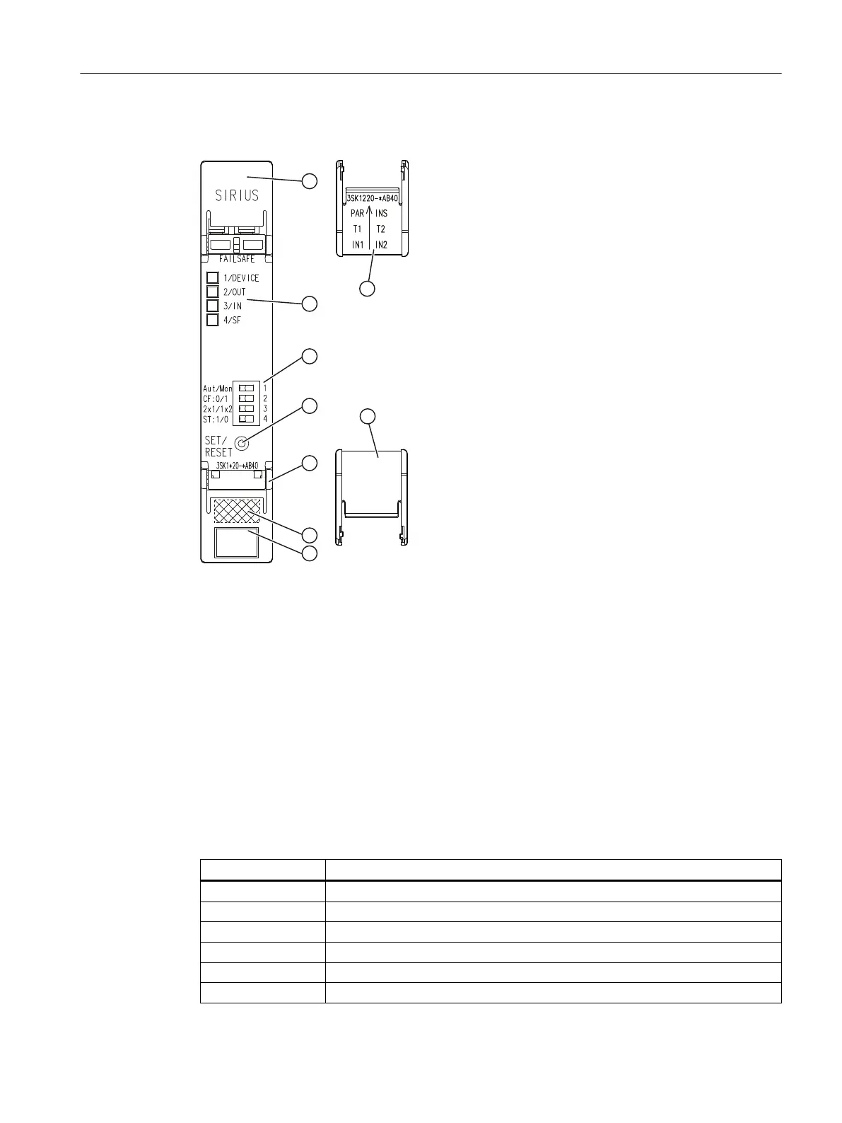
5.5.1.3 Design
① Top cover ap
② Top cover ap; internal inscription
③ Display LEDs
④ DIP switch
⑤ SET/RESET button
⑥ Bottom cover ap
⑦ Bottom cover ap; internal inscription
⑧ DataMatrix code
⑨ Device identication label
5.5.1.4 Terminal assignment
Terminal Explanation
IN1 Sensor channel 1
IN2 Sensor channel 2
PAR NO contact/NC contact evaluation
INS ON button circuit
T1 Test output 1 (for IN1, PAR)
T2 Test output 2 (for IN2, INF)
3SK1 / 3RQ1 devices
5.5 3SK1 input expansions
SIRIUS 3SK1 Safety Relays and 3RQ1 Positively-Driven Coupling Relays
Equipment Manual, 05/2021, A5E02526190021A/RS-AE/005 105

 Loading...


