5.3.3 Display of the operating state
Display of the operating state
The operating state and functioning of the device are indicated by an LED:
• (1) DEVICE
Operating states
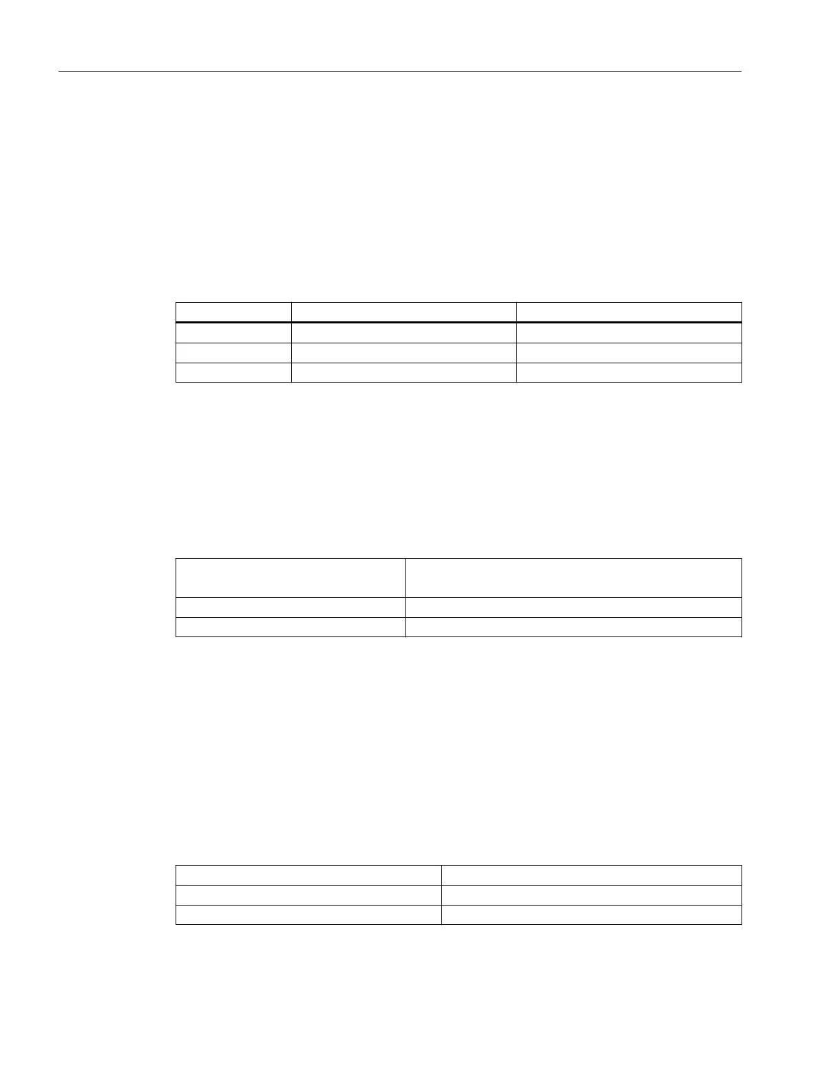
LED State Meaning
DEVICE Control supply voltage Safety-related outputs
OFF OFF Open
Green ON Closed
5.3.4 Function setting
Setting the activation (slide switch only for 24 V variants)
The interface input for activating the output expansion can be selected using a slide switch on
the front of the device.
Slide switch
Interface input
Top Outputs switch with time delay (as in basic unit)
Bottom Outputs switch instantaneously
When using an instantaneous basic unit, the slide switch must be in the instantaneous position
(bottom).
5.3.5 Output expansion 3SK1211
5.3.5.1 Device features
Article number
3SK1211-xBB00 24 V AC
3SK1211-xBB40 24 V DC
3SK1211-xBW20 110 ... 240 V AC / DC (wide-range supply)
x = 1: Screw-type terminal; x = 2: Spring-loaded (push-in) terminal
3SK1 / 3RQ1 devices
5.3 3SK1 output expansions
SIRIUS 3SK1 Safety Relays and 3RQ1 Positively-Driven Coupling Relays
90 Equipment Manual, 05/2021, A5E02526190021A/RS-AE/005

 Loading...


