8.2.6 Wiring rules for spring-loaded terminal (push-in system)
Notes on handling spring-loaded terminals (push‑in system)
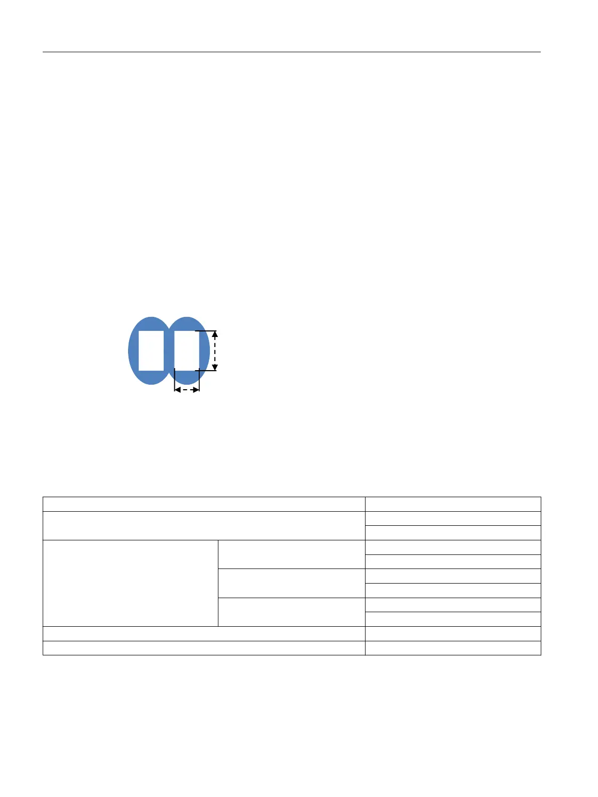
The terminal area of the spring-loaded (push-in) terminals is rectangular, and the maximum
overall dimensions of the conductor to be wired must not exceed 1.5 x 2.4 mm (control current
terminals).
Attention must be paid to the orientation of the terminal area, which may call for vertical tting
of rectangularly crimped cables.
To make optimum use of available terminal area, you are advised to choose a form of crimping
that creates a corresponding rectangular contour. Trapezoidal crimping is generally very highly
suitable in this case.
When use is made of a cable that utilizes the full overall height, the terminal's spring is
deected to the maximum. Therefore, removal of this cable may become a problem because it
requires further deection of the spring.
Control current terminals
Terminal area of control current terminals
8.2.7 Connection data for 3SK1 spring-loaded terminal (push-in system)
Connection data for ... Control current terminals
Connectable conductor cross-sections for solid cables 2 x 0.5 ... 2 x 1.5 mm²
(AWG
1)
: 20 ... 16)
Connectable conductor cross-sections for
exible cables
Without end sleeve 2 x 0.5 ... 2 x 1.5 mm²
(AWG
1)
: 20 ... 16)
With end sleeve (with and without
plastic sleeve)
2 x 0.5 ... 2 x 1.0 mm²
2)
(AWG
1)
: 20 ... 18)
With TWIN end sleeve ---
---
Cable stripping length 10 ... 11 mm
End sleeves according to DIN 46228‑4 with plastic sleeve 10 mm
1)
AWG: American Wire Gauge (AWG does not dene use of end sleeves)
2)
When 2 x 1.0 mm² end sleeves with a plastic sleeve are used, space problems may arise with the sleeves; as an alternative,
you are advised to use end sleeves without plastic sleeves
Connection
8.2 22.5 mm/17.5 mm devices
SIRIUS 3SK1 Safety Relays and 3RQ1 Positively-Driven Coupling Relays
160 Equipment Manual, 05/2021, A5E02526190021A/RS-AE/005

 Loading...


