4.3.11 Cascading
Cascading of safety relays is used for tripping safety relays in series.
Several safety functions can then be logically connected to a shared shutdown path. Several
safety-related outputs can be created for selective shutdown of drive elements.
The connection between the individual modules must be arranged on one side only, because
cascading from the last relay to the rst one would create a loop which would prevent starting.
Cascading is implemented within a control cabinet in a single-channel conguration; this is even
permissible with SIL 3 / PL e, because cable routing within a control cabinet is protected against
short-circuits and short-circuiting to P potential (fault exclusion in accordance with
ISO 13849-2).
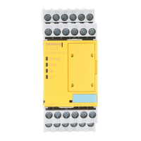
The 3SK1 Advanced device series oers an extremely convenient solution for cascading. Input
expansions can be easily connected to the evaluation unit by means of device connectors.
4.3.12 Startup testing
The sensor or protection equipment must be opened and closed again after the supply voltage
is restored before the enables for the 3SK1 safety relay can be switched through.
Startup testing ensures that any errors in the sensors are detected (again), because safety relays
lose their ability to store errors at zero voltage.
Unauthorized manipulation of the protection equipment can also be detected through startup
testing.
The plant operator decides whether startup testing should be performed (risk assessment). No
general statements apply.
Note
In the delivery state of 3SK1 safety relays, startup testing is deactivated.
4.3.13 Connection of actuators
Note
To achieve the Performance Level / Safety Integrity Level given in the following examples, the
actuators shown must be monitored in the feedback circuit of the corresponding safety relay.
Note
For capacitive and inductive loads, we recommend an adequate protective circuit. In this way,
electromagnetic interference can be suppressed and contact service life increased.
You can nd more information in the SIRIUS Innovations - SIRIUS 3RT2 Contactors/Contactor
Assemblies manual (http://support.automation.siemens.com/WW/view/en/60306557).
Safety systems - General information
4.3 Basic terminology
SIRIUS 3SK1 Safety Relays and 3RQ1 Positively-Driven Coupling Relays
48 Equipment Manual, 05/2021, A5E02526190021A/RS-AE/005

 Loading...

