Connection of magnetically operated switches
When connecting magnetically operated switches to the inputs, observe the information in
chapter Use of magnetically operated switches (Page 52).
5.1.3.6 Outputs
The safety relay has the following outputs:
• Safety-related outputs (relays), NO contacts: 13/14, 23/24, 33/34
• Non-safety-related outputs (semiconductor signaling circuit; relays), NC contacts: 41/42
5.1.3.7 Display of the operating state
Two LEDs and a slide switch indicate the operating state and functioning of the device:
• DEVICE
• OUT
LED displays
LED Operation
DEVICE OUT Line sup‐
ply
Sensor START button Safety-related out‐
put
Green Green ON Not pressed Pressed Closed
Green OFF Pressed --- Open
Green OFF Not pressed --- Open
Error
OFF OFF Cross-circuit or no power supply Open
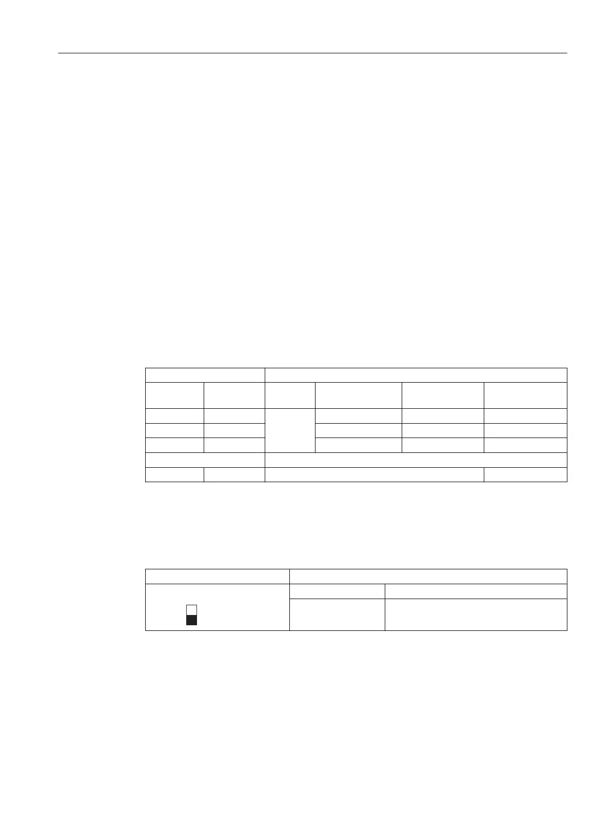
5.1.3.8 Function setting
Setting the functions
Slide switch
Start
AUTO Autostart
MONITORED Monitored start
In the delivery state, the slide switch is at the bottom (monitored start).
3SK1 / 3RQ1 devices
5.1 3SK1 standard
SIRIUS 3SK1 Safety Relays and 3RQ1 Positively-Driven Coupling Relays
Equipment Manual, 05/2021, A5E02526190021A/RS-AE/005 57

 Loading...


