14.3 Typical circuits
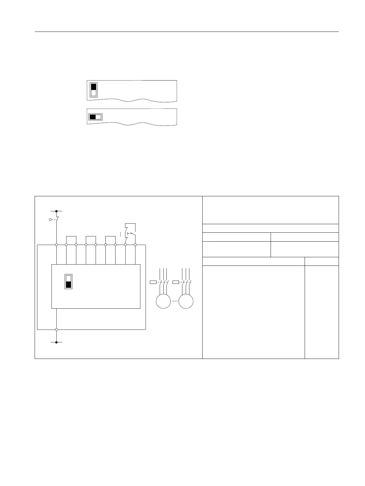
The black elds show the positions of the switches. Here, "Autostart" in each case.
$XWRVWDUW0RQLWRUHG6WDUW
$XWR
0RQLWRUHG
If use of the feedback circuit is not desired for the application, this has to be jumpered with the
corresponding test output.
Typical circuit for 3SK1111 Standard relay basic unit
Table 14-1 Typical circuit 1:
Single-channel, with monitored start
$XWR
0RQLWRUHG
/
/
)6
,1
$
,1,177,177
$
4
4Q
4
0
4Q
0
* For 3SK1111-.AB30 basic unit only
• Monitored start
• 3SK1111 Standard relay
• Sensor: 1 NC contact
Slide switch
Auto Monitored
— ON
Bottom
Up to PL in accordance with ISO 13849-1 c
Up to Safety Integrity Level (SILCL) to
IEC 62061
1
Circuit diagrams
14.3 Typical circuits
SIRIUS 3SK1 Safety Relays and 3RQ1 Positively-Driven Coupling Relays
Equipment Manual, 05/2021, A5E02526190021A/RS-AE/005 211

 Loading...


