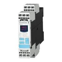
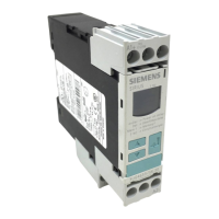
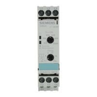
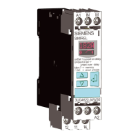
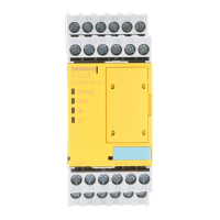
• 4 LEDs for status and function display
• 2 sensor inputs (channels 1 and 2)
• 1 input (cascading circuit)
• 1 input (START pushbutton circuit)
• NO contact/NC contact evaluation via external jumper (T1/PAR)
• Connecting interface for 3ZY12 device connectors
• Removable terminals
5.2.4 Function description
There is a 4-way DIP switch for function setting and 4 LEDs for status and function display on the
front of the 3SK1 Advanced basic units. A SET/RESET button can be used to load function
settings and to perform a device restart (reset). On commissioning, the devices runs a self-test
in which the internal electronics and rmware are checked for correct functioning. All internal
parts of the circuit are cyclically monitored for faults during operation. In the case of units with
semiconductor outputs, they cyclically run through a light/dark test for up to 2.5 ms
(dynamically) to verify their correct functioning. The safety relays can be expanded using 3ZY12
device connectors with input and output expansions.
3SK1 Advanced basic unit time-delayed only:
These basic units have 2 time-delayed and 2 instantaneous safety-related outputs (NO circuits)
or outputs switching to P potential.
Four LEDs and one DIP switch indicate the operating state and functioning of the device:
• (1) DEVICE
• (2) OUT
• (3) IN
• (4) SF
The four LEDs show the following:
• Operating mode: Diagnostics
• Conguration mode: DIP setting
For an explanation of the operating state display, see Section Display and diagnostics
(Page 185)
3SK1 / 3RQ1 devices
5.2 3SK1 Advanced
SIRIUS 3SK1 Safety Relays and 3RQ1 Positively-Driven Coupling Relays
68 Equipment Manual, 05/2021, A5E02526190021A/RS-AE/005

 Loading...

