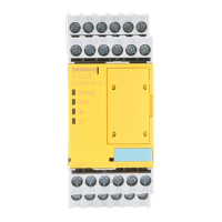
Terminal Explanation
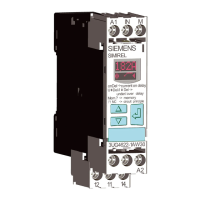
INF/S Feedback circuit/START button
T1 Test output 1 (for IN1)
T2 Test output 2 (for IN2)
T3 Test output 3 (for IN3)
1)
T4 Test output 4 (for INF/S)
13 - 14
23 - 24
33 - 34
Safety-related outputs (NO contact, relay contact)
41 - 42 Relay signaling circuits (NC contacts)
Floating: Sensors T1/IN1 and T2/IN2
Jumper T3/IN3
Non-oating Sensors IN1 and IN3
1)
Jumper T2/IN2
1)
For 24 V AC/DC variant only
5.1.3.5 Inputs
The device has either 3 or 4 inputs for safe signal processing: IN1, IN2 or IN3 (only 24 V devices
for connecting oating sensors) INF/S:
The inputs IN1 and IN2 can be operated in two-channel mode with cross-circuit detection. A
single-channel control is also possible and is described in chapter Typical circuits (Page 211),
tables 7- 1 to 7- 4.
If no feedback circuit is to be used in the application, this must be jumpered with the
corresponding test output.
Voltage variant 24 V:
Connecting oating sensors:
When oating sensors are used, sensor inputs T1/IN1 and T2/IN2 must be used and T3/IN3 must
additionally be jumpered for two-channel sensor connection.
Connecting non-oating sensors:
With non-oating sensors, cross-circuit detection must be deactivated.
This is implemented by the following pin assignment on the 3SK1111-.AB30:
IN1 and IN3 must be used as the input terminal for the two-channel non-oating sensor. In
addition, T2/IN2 must be jumpered.
Voltage variant 110 V ... 240 V AC/DC:
Only oating sensors can be connected to the 3SK1111-.AW20 device version.
The 2-channel sensor is connected via T1/IN1 and T2/IN2.
3SK1 / 3RQ1 devices
5.1 3SK1 standard
SIRIUS 3SK1 Safety Relays and 3RQ1 Positively-Driven Coupling Relays
56 Equipment Manual, 05/2021, A5E02526190021A/RS-AE/005

 Loading...

