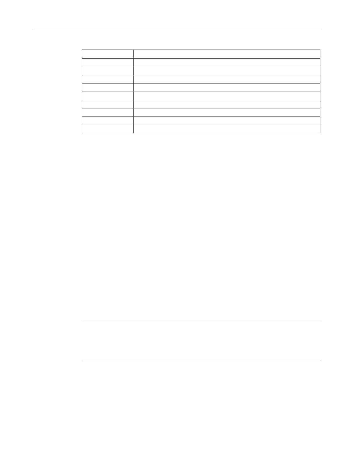
Terminal Explanation
IN2 Sensor channel 2
INS START pushbutton circuit
INF Feedback circuit
INK Cascading circuit
T1 Test output 1 (for IN1)
T2 Test output 2 (for IN2, INF)
Q1 Semiconductor output 1 (switching to P potential, 24 V DC)
Q2 Semiconductor output 2 (switching to P potential, 24 V DC)
QM1 Semiconductor signaling circuit 1 (switching to P potential, 24 V DC)
5.1.4.5 Inputs
The device has ve inputs for safe signal processing: IN1, IN2, INS, INF, INK:
• IN1: sensor input channel 1
• IN2: sensor input channel 2
• INS: START pushbutton circuit (start after rising and falling edge)
• INF: feedback circuit (checked for closed state: before switching on)
• INK: cascading circuit (cascading input/normal switching duty)
• The cascading circuit is AND-connected with the IN1 and IN2 sensor inputs.
• START button circuit and cascading circuit are activated with a static +24 V DC signal.
• With cross-circuit detection activated, the following inputs are checked for cross-circuits and
short-circuits to P: IN1/T1 to IN2/T2 and INF/T2. The inputs then receive their supplies from
the test outputs T1 and T2.
• If "without cross-circuit detection" is set on the device, inputs IN1 and IN2 are not checked for
cross-circuits. Inputs IN1 and IN2 must not be supplied via T1/T2 here, otherwise a fault will
be generated via input INF. It is therefore essential that inputs IN1 and IN2 are supplied via
an external + 24 V DC current source from which the device is also supplied.
• If the unit is parameterized to 2 x 1-channel with DIP switch 3, the sensor circuit that is not
used (T1/IN1 or T2/IN2) must be bypassed.
Note
Observe the following special points during commissioning of the 3SK1112 safety relay:
The cascading input must be connected to terminal A1 if it is not to be used.
Monitoring of the feedback circuits is not optional.
3SK1 / 3RQ1 devices
5.1 3SK1 standard
SIRIUS 3SK1 Safety Relays and 3RQ1 Positively-Driven Coupling Relays
Equipment Manual, 05/2021, A5E02526190021A/RS-AE/005 63

 Loading...


