5.1.4.6 Outputs
The safety relay has the following outputs:
• Q1, Q2: safety-related semiconductor outputs with dynamic monitoring, switching to P
potential
• QM1: non-safety-related semiconductor signaling circuit, switching to P potential
The safety-related semiconductor outputs and the safety-related semiconductor signaling
circuit are short-circuit-proof.
5.1.4.7 Display of the operating state
Four LEDs and one DIP switch indicate the operating state and functioning of the device:
• (1) DEVICE
• (2) OUT
• (3) IN
• (4) SF
The four LEDs show the following:
• Operating mode: Diagnostics
• Conguration mode: DIP setting
For an explanation of the operating state display, see Section Display and diagnostics
(Page 185)
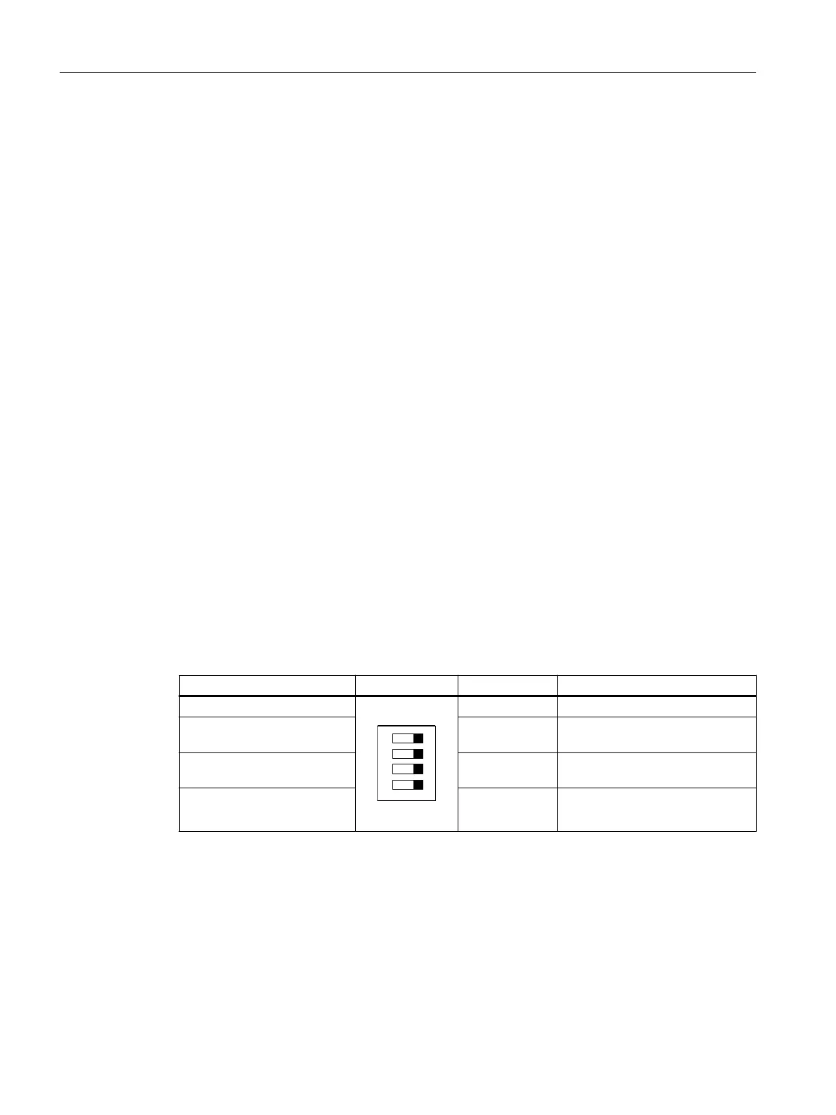
5.1.4.8 Function setting
Table 5-1 DIP switch
Switch position: left Schematic DIP switch No. Switch position: right
Autostart
1 Monitored start
Cross-circuit detection deacti‐
vated
2 Cross-circuit detection activated
2 x single-channel sensor con‐
nection
3 1 x two-channel sensor connec‐
tion
Start-up test ON 4 Start-up test OFF
3SK1 / 3RQ1 devices
5.1 3SK1 standard
SIRIUS 3SK1 Safety Relays and 3RQ1 Positively-Driven Coupling Relays
64 Equipment Manual, 05/2021, A5E02526190021A/RS-AE/005

 Loading...


