Using the cascading input
The cascading input must be controlled with a 24 V DC signal. The voltage source of the 24 V DC
signal must correspond to the voltage source of the safety relay's supply voltage (A1).
Note
Observe the following during commissioning of 3SK1 Advanced safety relays:
The cascading input must be connected to terminal A1 if it is not to be used.
Monitoring of the feedback circuits is not optional.
Parameterization "2 x single-channel"
If the unit is parameterized to 2 x single-channel with DIP switch 3, the sensor circuit that is not
used (T1/IN1 or T2/IN2) must be bypassed.
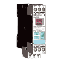
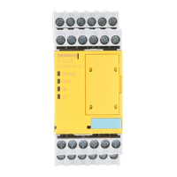
5.2.6 3SK1121 Advanced basic unit instantaneous (with relay outputs)
5.2.6.1 Device features
Article number
3SK1121-xAB40 24 V DC
x = 1: Screw-type terminal; x = 2: Spring-loaded (push-in) terminal
5.2.6.2 Function description
The 3SK1121 Advanced basic unit has three safety-related relay outputs and one non-safety-
related signaling circuit.
3SK1 / 3RQ1 devices
5.2 3SK1 Advanced
SIRIUS 3SK1 Safety Relays and 3RQ1 Positively-Driven Coupling Relays
70 Equipment Manual, 05/2021, A5E02526190021A/RS-AE/005

 Loading...

