5.2.5 Functions
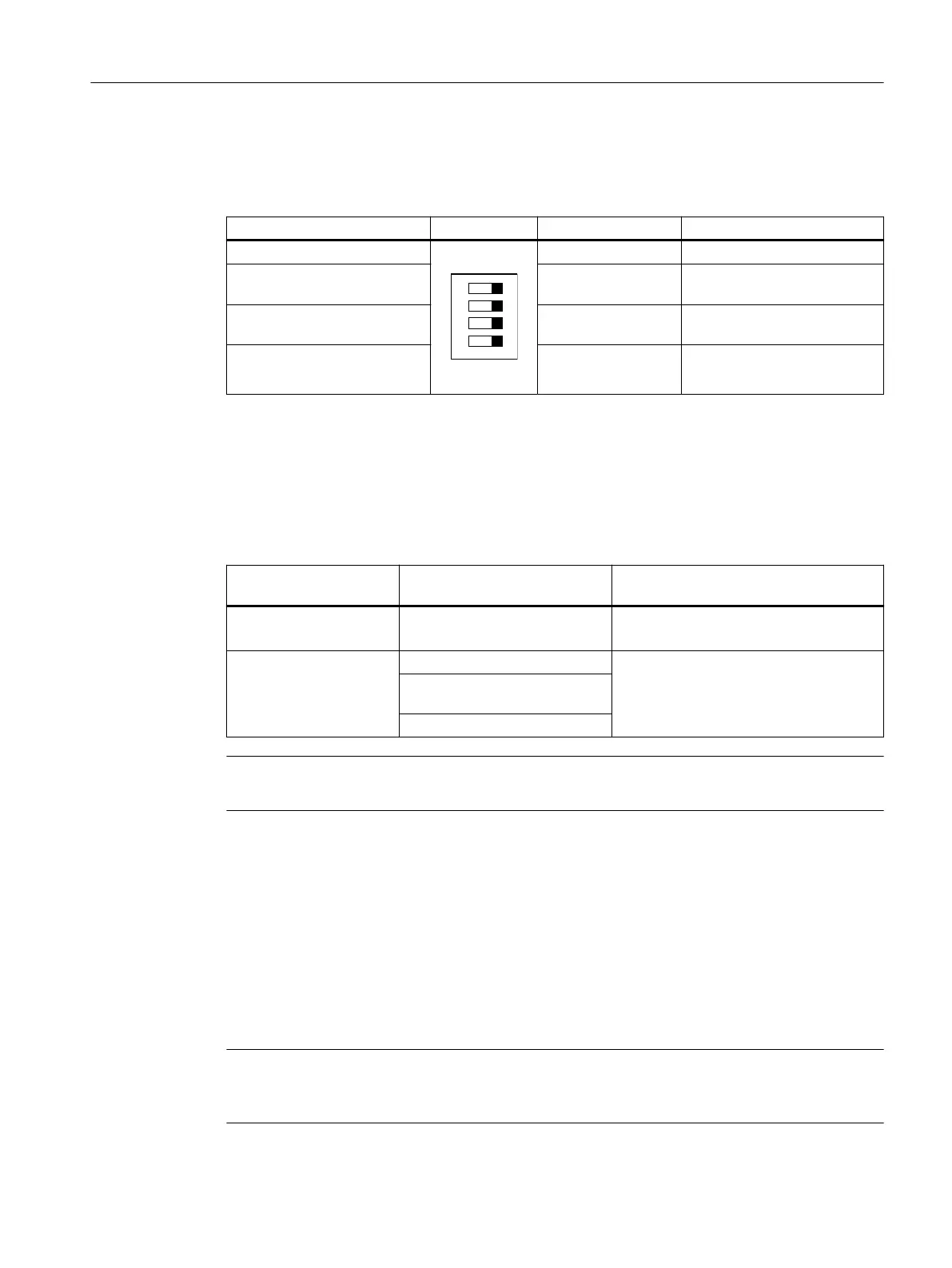
Table 5-3 DIP switch
Switch position: left Schematic DIP switch No. Switch position: right
Autostart
1 Monitored start
Cross-circuit detection deacti‐
vated
2 Cross-circuit detection activa‐
ted
2 x single-channel sensor con‐
nection
3 1 x two-channel sensor con‐
nection
Start-up test ON 4 Start-up test OFF
In the delivery state, all the DIP switches are in switch position: right.
Terminal parameterization:
Jumper on terminals T1/PAR = NO/NC evaluation
Table 5-4 SET/RESET button
Function of the SET/
RESET button
Status of the indicating LEDs Function
SET "DEVICE" LED ashing yellow
• Press key for about 1 s
The parameterization is loaded
RESET "DEVICE" LED red
• Press key for about 1 s
=> The device restarts without the
supply voltage having to be switched
o
"DEVICE" LED ashing green yel‐
low
"SF" LED red
Note
The SET/RESET pushbutton only triggers a reset for the device on which the button is pressed.
Potentiometer for time setting
Potentiometer for innite time setting of the time-delayed safety-related outputs on the
Advanced basic units (with time-delayed safety-related outputs).
• 3SK112.-.CB41 setting range: 0.05 ... 3 s
• 3SK112.-.CB42 setting range: 0.5 ... 30 s
• 3SK112.-.CB44 setting range: 5 ... 300 s
Note
The delay time ends when the voltage is disconnected. The time-delayed contacts change
switch position.
3SK1 / 3RQ1 devices
5.2 3SK1 Advanced
SIRIUS 3SK1 Safety Relays and 3RQ1 Positively-Driven Coupling Relays
Equipment Manual, 05/2021, A5E02526190021A/RS-AE/005 69

 Loading...


