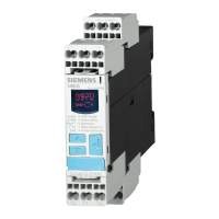
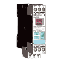
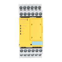
9.2 Explanation of the device's functions
Explanation of the device functions (DIP switches)
DIP
switch
Parameter Function
1 Start type
• Autostart: The safety-related outputs are switched to the active position as soon as the
switch-on condition is satised at the sensor inputs IN1, IN2, INF and INK. The START button
connecting terminal INS is not queried.
• Monitored start: The safety-related outputs are switched to the active position as soon as
the switch-on condition is met at the IN1, IN2, INF and INK sensor inputs and the START
button at the INS terminal is actuated (start with the falling edge).
2 Cross-circuit de‐
tection
Cross-circuit detection is only possible with oating sensors. The sensors must be connected
between T1 - IN1 and T2 – IN2. At the terminals IN1 and PAR (if used), the test signal of terminal
T1 is expected; at the terminals IN2 and INF , the test signal of T2 is expected. The device detects
a sensor fault if the signal at the terminals IN1, PAR or IN2, INF does not match the test signals
T1, T2.
Cross-circuit detection must be deactivated if electronic sensors such as light arrays or laser
scanners are connected. The 3SK1 now no longer monitors the sensor inputs for cross-circuit
detection. Usually, the outputs of safety sensors (OSSD) are already monitored for cross-circuits
in the sensor.
Devices with PAR terminals expect the test signal T2 at the parameterization input. A 24 V signal
at the PAR or INF terminals results in a fault (cross-circuit at the input).
3 Type of connec‐
tion
• 1 sensor with 2 contacts 1 x two-channel; NC/NC.
It is expected here that both contacts be open simultaneously.
With the additional connection of T1 to PAR, this DIP parameterization applies to ONE two-
channel sensor with NC/NO contacts.
• 2 sensors with one contact each 2 x single-channel; NC / NC.
In this case, both sensors are AND-connected. Simultaneity is not monitored.
4 Startup testing After a power failure, startup testing requires that the sensors at IN1 and IN2 are actuated once
by the system operator.
Conguration / operation
9.2 Explanation of the device's functions
SIRIUS 3SK1 Safety Relays and 3RQ1 Positively-Driven Coupling Relays
176 Equipment Manual, 05/2021, A5E02526190021A/RS-AE/005

 Loading...

