Terminal Explanation
IN1 Sensor channel 1
IN2 Sensor channel 2
PAR NO contact/NC contact evaluation
INS START pushbutton circuit
INF Feedback circuit
INK Cascading circuit
T1 Test output 1 (for IN1, PAR)
T2 Test output 2 (for IN2, INF)
13 - 14
23 - 24
33 - 34
Safety-related outputs (NO contact, relay contact)
41 - 42 Semiconductor signaling circuits (NC contact, relay contact)
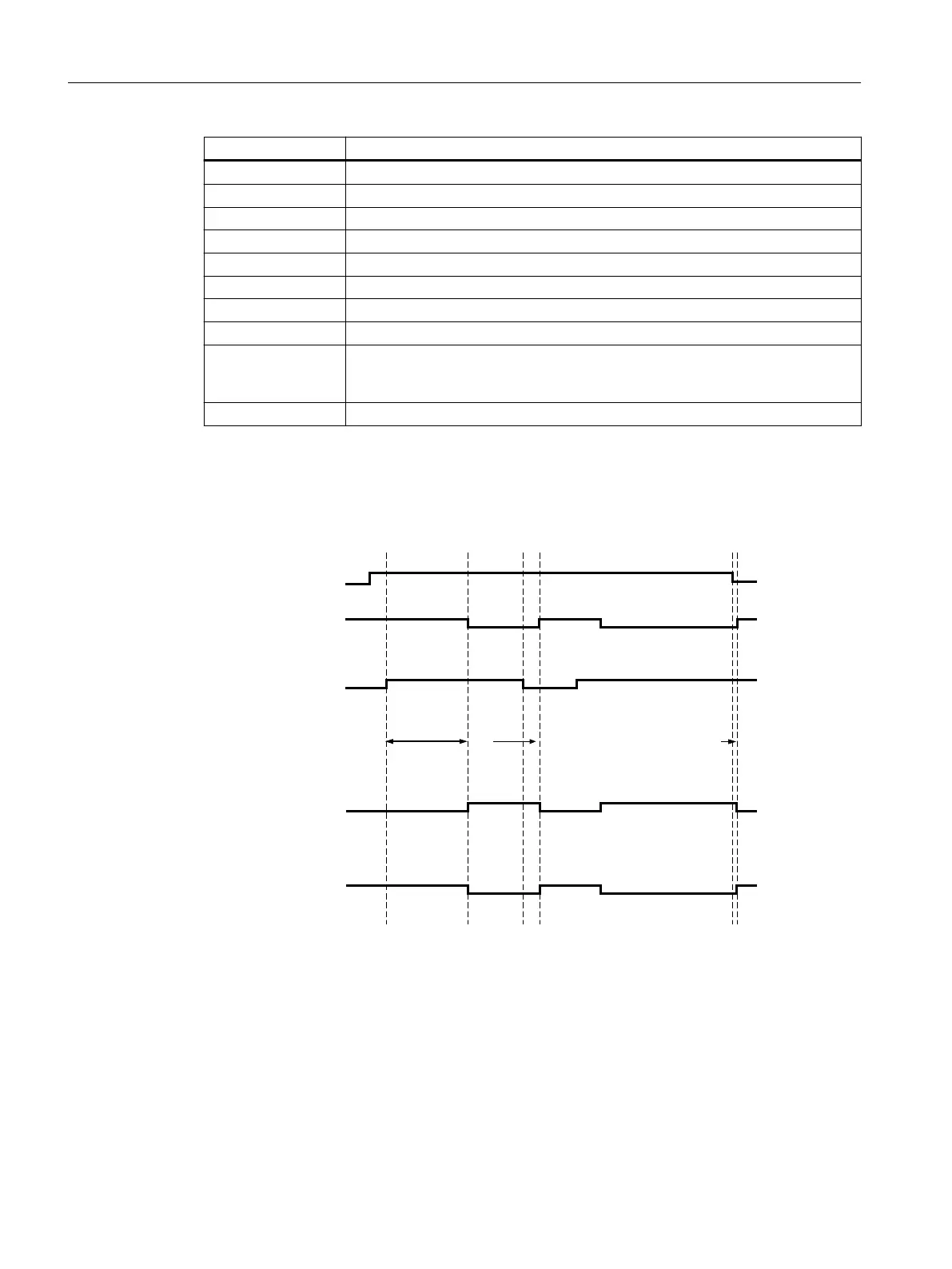
State diagram 3SK1121
INF (feedback
circuit)
A1/A2
Safety-related
output
Signaling
circuit
3SK1121-xAB40 autostart
InputsOutputs
IN1/IN2
(sensor circuit)
or
INK
85 ms
35 ms
35 ms
3SK1 / 3RQ1 devices
5.2 3SK1 Advanced
SIRIUS 3SK1 Safety Relays and 3RQ1 Positively-Driven Coupling Relays
72 Equipment Manual, 05/2021, A5E02526190021A/RS-AE/005

 Loading...


