Terminal Explanation
IN1 Sensor channel 1
IN2 Sensor channel 2
PAR NO contact/NC contact evaluation
INS START pushbutton circuit
INF Feedback circuit
INK Cascading circuit / normal switching duty
T1 Test output 1 (for IN1, PAR)
T2 Test output 2 (for IN2, INF)
Q1 Instantaneous safety-related output 1
(switching to P potential, 24 V DC)
Q2 Instantaneous safety-related output 2
(switching to P potential, 24 V DC)
Qt1 Time-delayed safety-related output 1
(switching to P potential, 24 V DC)
Qt2 Time-delayed safety-related output 2
(switching to P potential, 24 V DC)
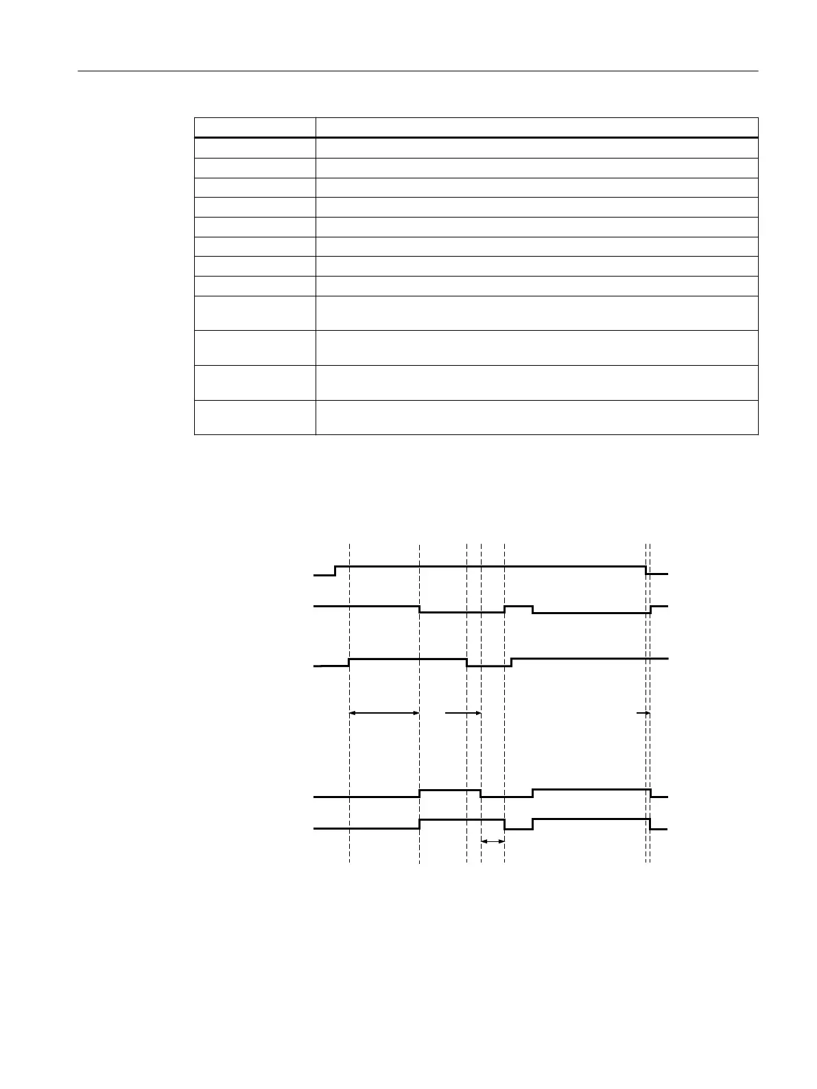
State diagrams 3SK1122-xCB4y
INF (feedback
circuit)
A1/A2
Safety-related
outputs
Safety-related
outputs
tv
3SK1122-xCB4y autostart
Inputsoutputs
IN1/IN2
(sensor circuit)
or
INK
150 ms 0 ms
tv
80 ms
3SK1 / 3RQ1 devices
5.2 3SK1 Advanced
SIRIUS 3SK1 Safety Relays and 3RQ1 Positively-Driven Coupling Relays
Equipment Manual, 05/2021, A5E02526190021A/RS-AE/005 83

 Loading...


