Cabinet Design and EMC Booksize
9.4 Arrangement of components and equipment
Booksize power units
Manual, (GH2), 06/2008, 6SL3097-2AC00-0BP6
517
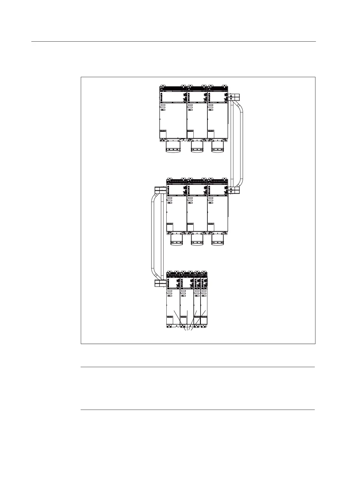
Multiple-tier configuration
$FWLYH
/LQH
0RGXOH
0RWRU
0RGXOH
0RWRU
0RGXOH
0RWRU
0RGXOH
0RWRU
0RGXOH
0RWRU
0RGXOH
0RWRU
0RGXOHV
'&OLQN
DGDSWHU
'&OLQN
DGDSWHU
Figure 9-8 Example of a three-tier configuration with components between 50 and 200 mm wide
Note
When the power supply input is on the right-hand side of the drive line-up (e.g. in a multiple-
tier configuration), the above rules apply in reverse.
This means that: The Motor Modules are arranged in order of power from the highest power
to the lowest power followed by the DC link components, such as the Braking Module.
 Loading...


