Cabinet Design and EMC Booksize
9.6 Connection systems
Booksize power units
534 Manual, (GH2), 06/2008, 6SL3097-2AC00-0BP6
Note
Measures must be taken on site to relieve strain on the cables.
Max. permissible cable tension in the connection direction: 100 N
With these variants, the shield for the brake connection wires must be laid with the cable
shield.
3. Securing a shield contact constructed by the customer on the shield plate.
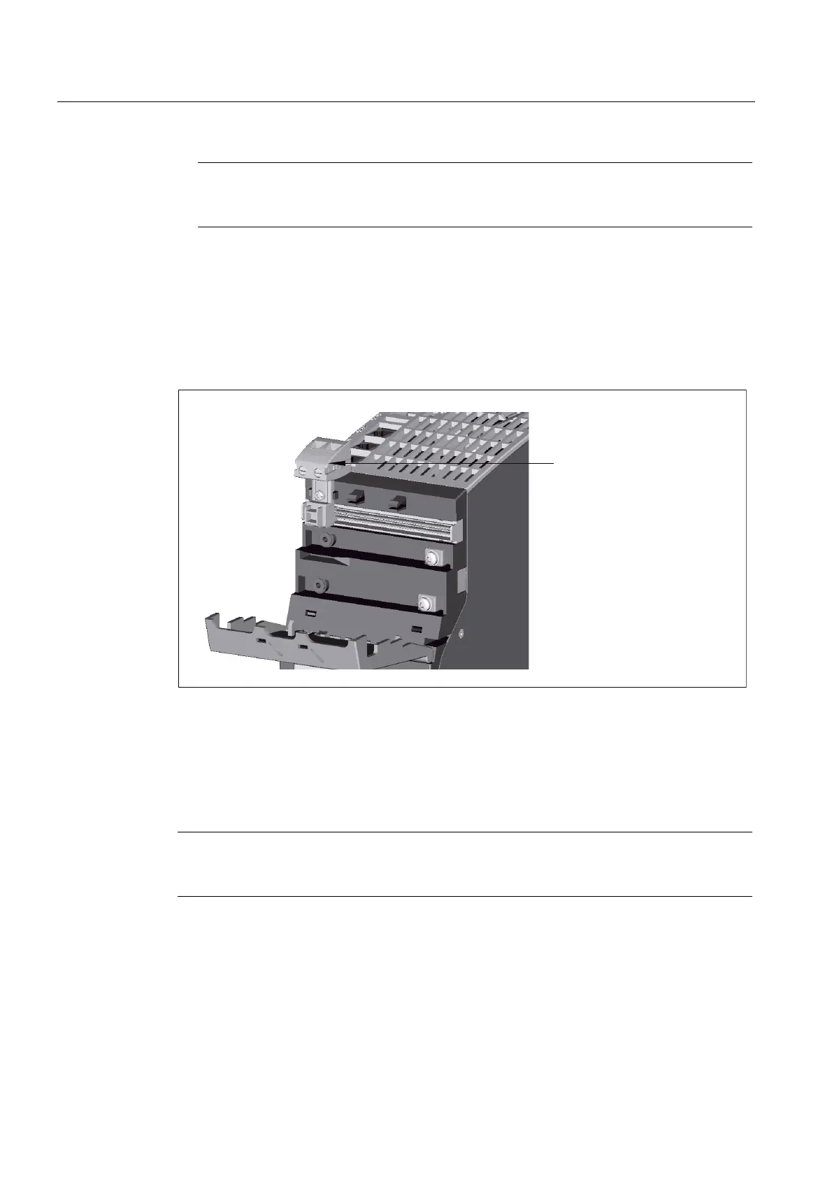
9.6.5 24 V terminal adapter
9WHUPLQDODGDSWHUIRU
FRQGXFWRUFURVVVHFWLRQPPt
Figure 9-15 24 V terminal adapter
The terminal adapter can be fitted to any power unit. A recess must be provided for this
purpose on the protective cover of the DC link using suitable pliers. The terminal adapter is
snapped on and secured with a screw SHR, PT-TORX K 30-3, 0X16-ST-A2F
WN1452/EJOT/0.5 Nm.
EJOT: http://www.ejot.de/
Note
The 24 V terminal adapter can only be installed on the component on the far left because all
other areas are occupied by the red jumpers.
24 V terminal adapter for a conductor cross-section of 6 mm
2
Terminal adapter and screw are supplied with the Line Modules and Control Supply Modules.
 Loading...


