Installation
7.4 Connecting SITOP UPS1100 battery modules to the UPS module
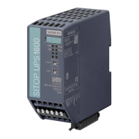
SITOP UPS1600 / BAT1600 / UPS1100
218 Equipment Manual, 07.2021, A5E37775406-11-76
Fuses F1/F2 (F2 only for 7/12 Ah)
Screw to replace the battery (Torx T10)
Connecting a SITOP UPS1100 battery module
1. Connect the SITOP UPS1600 with the battery module at power terminal ① and at signal
terminal ②.
2. Insert the fuse ③.
The connected battery module is automatically detected.
Please note that identifying a SITOP UPS1100
battery module at a SITOP UPS1600 after
inserting the connecting cables or after inserting the fuse in the SITOP UPS1100 battery
module can typically take 20 seconds, but up to 2 minutes.
Connecting several SITOP UPS1100 battery modules
In hazardous zones (ex-applications), it is absolutely prohibited that SITOP UPS1100 battery
modules are connected in parallel.
To extend the power failure buffering time, up to 6 identical SITOP UPS1100 battery modules
can be connected to a SITOP UPS1600.

 Loading...
