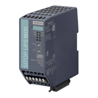
Description, device design, dimension drawing
2.4 Operating displays and signaling
SITOP UPS1600 / BAT1600 / UPS1100
44 Equipment Manual, 07.2021, A5E37775406-11-76
LED 8 (Ethernet LED /P1)
Signaling
6EP4134-3AB00-2AY0
6EP4136-3AB00-2AY0
Device not connected with controller
Device connected with controller, no activity
Green/yellow, alternat-
ing
Device connected with controller, send/receive data (RX/TX)
Device connected with controller, active communication (RX/TX)
LED 8 is active only for ... -2AY0.
2.4.1.2 Relay outputs
Figure 2-21 Signal connector connection schematic
Rel.1 (changeover contact):
Energized state: Normal operation (X2.2 - X2.3)
Deenergized state: Buffer mode or off
Rel.2 (changeover contact):
Energized state: Buffer mode is possible (X2.5 - X2.6)
Deenergized state: Not ready for buffering
Cycle 0.25 Hz: Battery defective or different – or more than 6 battery modules connected.
If the buffer time is not reached, only Rel.3 (< 85 %) is in the quiescent state.
In buffer mode, signal "alarm" signifies that the battery voltage has dropped to < 20.5 V and a
forced shutdown is immediately pending to protect the battery. After the battery has been
shut down as a result of overload, short-circuit, deep discharge protection or expired buffer
time, the red LED (alarm) goes dark, relay contact X2.4 - X2.5 remains closed.
Rel.3 (NO contact):
Energized state: Buffering of the selected buffer time is possible, or charge state > 85 %.

 Loading...
