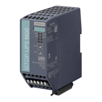
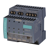
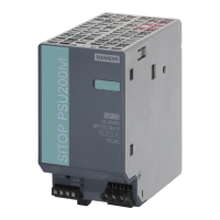
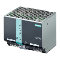
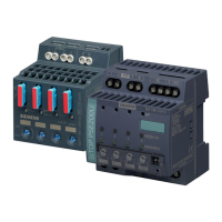
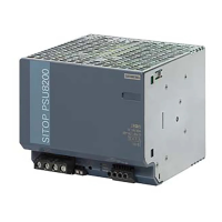
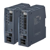
Description, device design, dimension drawing
2.4 Operating displays and signaling
SITOP UPS1600 / BAT1600 / UPS1100
46 Equipment Manual, 07.2021, A5E37775406-11-76
States of the LEDs
Signaling
6EP4132-0JA00-0AY0 (2.5 Ah)
6EP4133-0GA00-0AY0 (3.2 Ah)
6EP4134-0JA00-0AY0 (7.5 Ah)
6EP4135-0GE00-0AY0 (12 Ah)
6EP4137-0GE00-0AX0 (38 Ah)
Module runs up, DC-UPS defective (critical hardware fault)
Flashing green
(0.25/0.25)
Battery is being replaced (button pressed, reset service life)
Battery successfully replaced (LED flashes for 5 s)
Battery replacement recommended (SoH ≤ 20 %)
Flashing yellow
(0.25/0.25)
End of the battery service life reached (SoH = 0 %) or battery test
negative → battery must be replaced, buffer mode possible
Temperature outside the valid range, communication cable interrupted or
different battery types being used → restricted charge operation
Selected buffer time cannot be attained
Battery replacement canceled (LED flashes for 5 s)
Fuse ruptured/not inserted, power cable interrupted, 1 battery in the mod-
ule is not connected, battery pack voltage is not symmetrical or reset button
2.4.3 SITOP UPS1100
Figure 2-22 Example 6EP4131-0GB00-0AY0
States of the LEDs
Signaling
6EP4131-0GB00-0AY0 (1.2 Ah)
6EP4132-0GB00-0AY0 (2.5 Ah)
6EP4133-0GB00-0AY0 (3.2 Ah)
6EP4133-0JB00-0AY0 (5 Ah)
6EP4134-0GB00-0AY0 (7 Ah)
6EP4135-0GB00-0AY0 (12 Ah)
Module runs up, DC-UPS defective (critical hardware fault)
Battery outside the permitted temperature range
Selected buffer time cannot be attained
Battery module fault, maintenance required (incorrect polarity, battery
module not connected, high ohmic battery module connection, battery
deep discharged, fuse defective/ruptured, asymmetrical cell voltage, battery

 Loading...
