Mounting/removing
5.3 SITOP UPS1100
SITOP UPS1600 / BAT1600 / UPS1100
Equipment Manual, 07.2021, A5E37775406-11-76
195
5.3 SITOP UPS1100
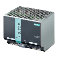
Installing the device in a housing or a control cabinet
The SITOP UPS1100 battery modules are built-in units. They must be installed in a housing
or control cabinet where only qualified personnel have access.
All devices are suitable for direct wall mounting.
Devices 6EP4131-0GB00-0AY0 (1.2 Ah), 6EP4132-0GB00-0AY0 (2.5 Ah), 6EP4133-0GB00-
0AY0 (3.2 Ah) and 6EP4133-0JB00-0AY0 (5 Ah) can also be snapped onto a DIN rail TH35×15
(EN 60715), and device 6EP4131-0GB00-0AY0 (1.2 Ah) also onto a DIN rail TH35×7.5
(EN 60715).
The lower part of the control cabinet or the coolest location in the control cabinet should be
chosen as mounting location.
When the device is installed in a hazardous zone (II 3G nA IIC T4 Gc), not permissible for
6EP4133-0JB00-0AY0 (5 Ah), then this must be installed in a distribution box with degree
of protection IP54 or higher. This distribution box must comply with the requirements of
In hazardous zones, it is not permissible that UPS1100 battery modules are connected in
Mounting
See Chapter Dimensions and weight for the holes for wall mounting SITOP UPS1100
(Page 54).
To mount the device on a standard mounting rail, place it with the standard mounting rail
guide at the upper edge of the DIN rail and snap it in downwards. If this is too difficult, push
the device downwards while pressing on the rail as described for "Removal".
Note
The fuses should be inserted in the fuse holder only when commissioning the device
(charged batteries).
 Loading...