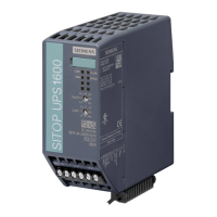
Description, device design, dimension drawing
2.3 Operator controls
SITOP UPS1600 / BAT1600 / UPS1100
38 Equipment Manual, 07.2021, A5E37775406-11-76
This can occur if the UPS was remotely shut down via the interface.
V1.1 and SITOP UPS1600 Version V2.2.2, when starting from the
e is identified when powering-up. After the set time "Shut down PC on
power failure" elapses, the PC is correctly powered down and switched off.
Setting the charge current (pins 10 / 11 / 12)
For third party batteries, the magnitude of the charge current can be changed by inserting
jumpers between terminals X2.10 (-) and X2.11 or X2.12. These settings are only effective if
the rotary coding switch REN is not set to (V
THR ≠ REN).
Table 2- 5 Charge current for SITOP UPS1600 without communication or SITOP UPS1600 USB/PN in
the manual mode (V
THR ≠ REN)
SITOP UPS1600
SITOP UPS1600
Terminal X2.11 Terminal X2.12 Charge volt-
*1)
*1)
*1)
Table 2- 6 Charge current for SITOP UPS1600 USB/PN in the remote mode (VTHR = REN)
SITOP UPS1600
SITOP UPS1600
SITOP UPS1600
Charge voltage
Comment
The charge current is automatically reduced if the input voltage of the UPS1600 falls below
24 V DC, or the ambient temperature exceeds 40 °C. In this case, the maximum charge
current is reduced as follows:
10 A: 3 A → 2 A
20 A: 4 A → 3 A
40 A: 5 A → 3 A

 Loading...
